In this project, we will design a unique door lock that can be operated without a key card, entry password or biometric identification. A smartphone is the key to locking and unlocking the door via Bluetooth.
This door uses a solenoid lock, which relies on a deadbolt for electrical locking and unlocking. It also has LEDs to indicate whether the door is locked or unlocked and triggers a buzzer for audible notifications. A vibration sensor produces an alert signal, protecting the door against unauthorized or forced access.
We will use an Arduino NANO board and will need a smartphone with Bluetooth connectivity for this project. Let's start with the block diagram, followed by the circuit diagram.
System block diagram
The main building blocks of the system include:
- An Arduino NANO board
- The HC05 Bluetooth Module
- A relay
- A solenoid lock
- A 12V buzzer.
We will also use some other blocks, with:
- LEDs
- A mini doorbell
- Vibration sensors
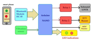
A block diagram of the smartphone-operated door lock.
1. The Smartphone with Bluetooth connectivity to transmit commands through the phone to lock or unlock the door.
2. The Bluetooth module sends commands from the user's smartphone to lock or unlock the door. The Bluetooth application sends these signals to the Arduino board via serial communication.
3. A vibration sensor is used to detect movement or vibrations in the door when it is locked. If the sensor detects strong vibrations, it sends an alert to the Arduino board.
4. The relays: Relay 1 activates (energizes) the solenoid lock. 12V is required to power the internal solenoid coil. Relay 2 also uses 12V, but is used to power the large buzzer.
5. The lock solenoid is used to lock the door
6. The large 12V buzzer generates an alert if someone tries to open the door by force when it is locked (without using your smartphone).
7. The mini doorbell alerts you whenever the door is locked or unlocked, generating a long or short beep respectively.
8. LEDs: Green and red LEDs indicate whether the door is locked or unlocked.
Required components:

The solenoid lock.
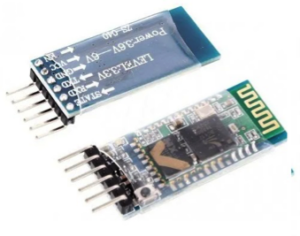
The HC05 Bluetooth Module.
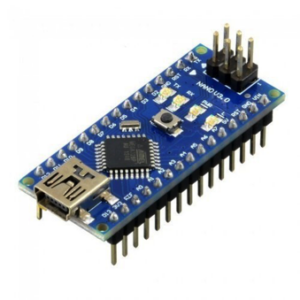
The Arduino NANO board.
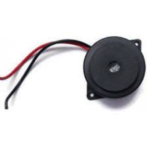
The big buzzer (12 V).
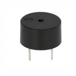
The mini buzzer (5 V).
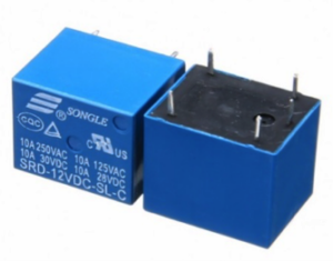
The relay – 12V PCB mount.
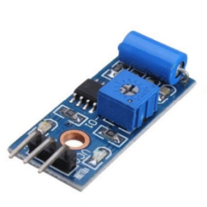
The vibration sensor module.
Schematic diagram:
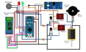
The complete circuit diagram of the smartphone operated door lock.
Circuit connections:
The HC05 Bluetooth Module has four pin connections: VCC, GND, Tx and Rx.
- Arduino provides the VCC pin with 5V
- The GND pin connects to common circuit ground
- The Tx and Rx pins connect to the Arduino digital pins D11 and D12, respectively
- Red and green LEDs connect to digital IO pins D9 and D10
- The digital IO pins, D7 and D8, activate the Relay 1 and Relay 2 coils through the transistors
- Both BC547 NPN transistors are connected in switch configuration and their collector output drives the relay coil
- The Relay 1 NO output activates the bells. The output of Relay 2 NO energizes the solenoid coil
- The common terminals (C) of both relays are supplied with 12 V (which is supplied to both the buzzer and solenoid lock)
- 5V mini buzzer connects to digital pin D5
The vibration sensor module has three pin connections: VCC, GND, and D0.
- Arduino provides the VCC pin with 5V
- The GND pin connects to common circuit ground
- The D0 pin connects to the Arduino digital pin D6
- The Arduino's VIN pin receives 12V input, thus generating 5V using its built-in 5V voltage regulator. This 5V is then supplied to the other modules.
Circuit Operation:
The circuit starts working when it is supplied with 12 V. Initially, the solenoid is in the locked position and the red light comes on to indicate that the door is locked.
To get started, open the Bluetooth app on your smartphone and pair it with the HC05 module (enter the default password, 1234). Once complete, the HC05 module flashes slowly and is ready to receive commands.
Then send the “ULCK” command to unlock the door from your smartphone’s Bluetooth app. The HC05 module will receive this command and transmit it serially to the Arduino via the Tx-Rx pins.
Upon receiving the command, the Arduino will send Logic 1 to pin D8, turning on Relay 2. This activates the solenoid and the door unlocks. At the same time, Arduino sends:
- Logic 1 to pin D9, turning on the green LED, signaling that the door is unlocked
- Logic 0 to pin D10, turning off the red LED (only used when the door is locked)
- Logic 1 to pin D5 for one second, indicating for the mini buzzer to generate a long beep, signaling that the door is unlocked
To lock the door, send the “LOCK” command. The HC05 module will receive this command and pass it to the Arduino. The Arduino then turns off Relay 2 by sending Logic 0 to pin D8, which disables the solenoid and locks the door.
Arduino also ships:
- Logic 1 to pin D5 for half a second, which generates a short mini-bell beep, indicating that the door is locked. Erase the green led by
- Logic 1 to pin D10, turning on the red LED, signaling that the door is locked
- Logic 0 to pin D9, turning off the green LED (only used when the door is unlocked)
When the door is locked and the vibration sensor detects any type of shock, force or vibration, it provides an alert signal via Logic 1 to the Arduino. Once received, the Arduino will send Logic 1 to pin D7, which turns on Relay 1, producing an alarm from the large 12V buzzer,
This circuit operation works because of the program that is downloaded into the internal FLASH of the Arduino's ATMega328. The program is written in C/C++ language and compiled in the Arduino IDE software.
The program file (code) must be downloaded (uploaded) into the 32 KB program memory (FLASH) of the ATMega328.
Software program:
#include
SoftwareSerial BT_serial(11,12);
char recved_code(5);
char block_code(5) = “BLOCK”;
char unlock_code(5) = “ULCK”;
int i=0,sirene_rly=7,buz=5;
int lock_rly=8,lock_led=10,un lock_led=9;
int porta_vibr_sensor=6;
int lock_flag=0,unlock_flag=1;
null configuration
{
// put your configuration code here, to run once:
BT_serial.begin(9600);
Serial.begin(9600);
pinMode(siren_rly,OUTPUT);
pinMode(buz,OUTPUT);
pinMode(lock_led,OUTPUT);
pinMode(lock_rly,OUTPUT);
pinMode(unlock_led,OUTPUT);
pinMode(door_vibr_sensor,INPUT);
digitalWrite(lock_rly,LOW);
digitalWrite(unlock_led,LOW);
digitalWrite(lock_led,1);
digitalWrite(buz,0);
digitalWrite(sirene_rly,LOW);
}
empty loop
{
int porta_vib_sensor_stat,lock_sensor_stat;
door_vib_sensor_stat = digitalRead(door_vibr_sensor);
if((door_vib_sensor_stat==0) && (lock_flag==1))
{
digitalWrite(siren_rly,HIGH);
Serial.println(“attempt to break down the door”);
}
if(BT_serial.available)
{
recved_code(i) = BT_serial.read ;
Serial.print(received_code(i));
me++;
}
if(i==4)
{
Serial.print(received_code);
if(strcmp(lock_code,recved_code)==0)
{
digitalWrite(lock_rly,LOW);
digitalWrite(buz,1);
delay(1000);
digitalWrite(buz,0);
lock_flag=1;
unlock_flag=0;
BT_serial.print(“Door locked”);
digitalWrite(lock_led,HIGH);
digitalWrite(unlock_led,LOW);
}
if(strcmp(unlock_code,recved_code)==0)
{
digitalWrite(lock_rly,HIGH);
digitalWrite(buz,1);
delay(500);
digitalWrite(buz,0);
unlock_flag=1;
lock_flag=0;
BT_serial.print(“Door unlocked”);
digitalWrite(lock_led,DOWN);
digitalWrite(unlock_led,HIGH);
}
l=0;
}
}
Video link: