In a previous tutorial we discussed MIT App Inventor, a popular online platform for building mobile apps using visual programming. The platform is useful for quickly prototyping Internet of Things (IoT) applications and simple embedded systems that interact with mobile devices.
We have already reviewed the architecture and user interface of the platform. Its visual programming platform is ideal for building beginner to intermediate mobile apps that interact over Wi-Fi or Bluetooth.
Now we will use MIT APP for mobile application development, integrating our new application with embedded electronics. In this tutorial, we will control an LED light using Arduino and a mobile app developed using MIT App Inventor. The mobile app will communicate with the Arduino via Bluetooth using the HC-05 Bluetooth module.
To begin, we will build a mobile application and transmit data from it to the Arduino using Bluetooth. Next, we will learn how data received over Bluetooth can be used to manipulate the Arduino circuit.
Building electronic and IoT applications controlled by mobile devices
When designing the circuit and firmware of the IoT device, we must also consider the mobile application. The application is the interface or medium that we will use to control an IoT device or access its wireless resources. Therefore, evaluating how the microcontroller will interact with our application is important.
For example, how will the microcontroller connect to the mobile application? What data will be exchanged? What IoT resources will be accessed? Mobile app development goes hand in hand with firmware development. As a result, the microcontroller firmware must be designed according to the intended interactions with the mobile application.
Additionally, it is essential to discover the functionality of the mobile app. What do you want it to control in terms of the IoT device? And how will your user interface behave? Once we are clear about the application functionality and user interface, we must determine the application logic. The IoT device will communicate data to the mobile application, or the mobile application will transmit some data to the device. In each scenario, you need to determine the type and range of data and operations to be conducted.
When building electronic or IoT applications that will be controlled through a mobile application, we must:
1. Design the IoT device circuit.
2. Program the device firmware considering its interaction with the mobile application.
3. Build the mobile app interface.
4. Develop mobile app logic based on device interaction.
5. Test the device and all its interactions with the mobile app.
When using MIT App Inventor, the mobile application's interaction with the microcontroller will be done via Bluetooth or Wi-Fi.
Required components
To build the circuit for this application, you will need the following components.
- Arduino UNO/Arduino MEGA x1
- LEDx1
- 330Ω resistor x1
- HC05 x1 Bluetooth Module
- Breadboard x1
- Connecting wires or Dupont wires
- A smartphone
Connecting the circuit
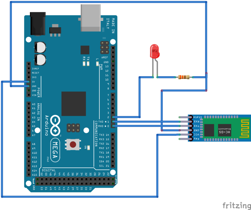
First, we must assemble the IoT device circuit. We will start by connecting an LED to the Arduino so that it can supply current to the light. To do this, connect the LED's anode to the Arduino's GPIO2 pin and connect the LED's cathode to ground through a 330 ohm series resistor.
Since we want to control the LED, we will need to create a way for the Arduino to communicate with our mobile app. The Arduino can communicate with the application (which is on a smartphone) via Bluetooth or Wi-Fi. We will use Bluetooth.
We are also using the Arduino UNO (or Arduino MEGA), which does not have built-in Bluetooth or Wi-Fi functions. So, we need to interface the HC-05 Bluetooth module with Arduino so that it can communicate with our application. To interface the HC-05 Bluetooth module with Arduino, connect the RX and TX pins of the HC05 module with the TX (GPIO1) and RX (GPIO0) of the Arduino, respectively. Connect the VCC and GND pins of the HC05 module with the 5V output and ground pins of the Arduino, respectively.
Circuit Diagram

Programming the microcontroller
When programming the microcontroller, we must consider the interaction of the mobile application with the IoT device. The app will turn the LED on or off on the Arduino.
The mobile application must send a '1' data value via Bluetooth whenever a user turns the LED ON and send a '0' data value via Bluetooth whenever a user turns the LED OFF.
The microcontroller firmware will “look” for an input data value or command from the Bluetooth application and set the digital output on the pin depending on whether the LED is wired HIGH or LOW (based on the input value).
Note that the firmware application logic depends entirely on the circuit design. Since the LED is connected in such a way that the Arduino supplies current, we must set the HIGH pin to turn on the LED and the LOW pin to turn off the LED.
The sketch
command char = 0;
empty configuration {
Serial.begin(9600);
pinMode(2, OUTPUT);
}
empty loop {
if(Serial.available > 0){
command = Serial.read;
Serial.print(“Command received by Buetooth: “);
Serial.println(command);
if(command == '1'){digitalWrite(2, HIGH); Serial.println(“LED ON”);}
else if(command == '0'){digitalWrite(2, DOWN); Serial.println(“LED OFF”);}
}
}
Load this sketch before making circuit connections or remove the VCC and GND connections from the Arduino with the HC05 while loading the sketch. Otherwise, you may encounter an error because the same UART port is shared between the computer and the HC05 Bluetooth module.
Building an app using MIT App Inventor
The mobile app requires two functions to properly control the LED on the Arduino. One must connect to the Arduino via Bluetooth and the other must turn the LED on and off.
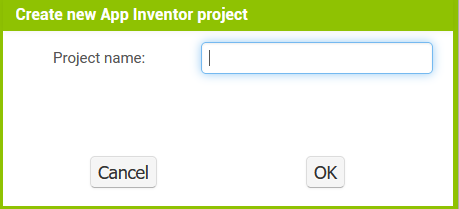
To build the app, log into the MIT App Inventor platform and create a new project by navigating to Projects->Start New Project.

Give the project a name like 'LEDOnOff' or 'LEDControlBluetooth' and click OK.
When creating a new project, you will see a blank screen. Select the screen and change its title to indicate the purpose of the application.

Now, we will need to build the user interface of our mobile app. The user interface allows users to connect to Arduino via Bluetooth to control the LED.
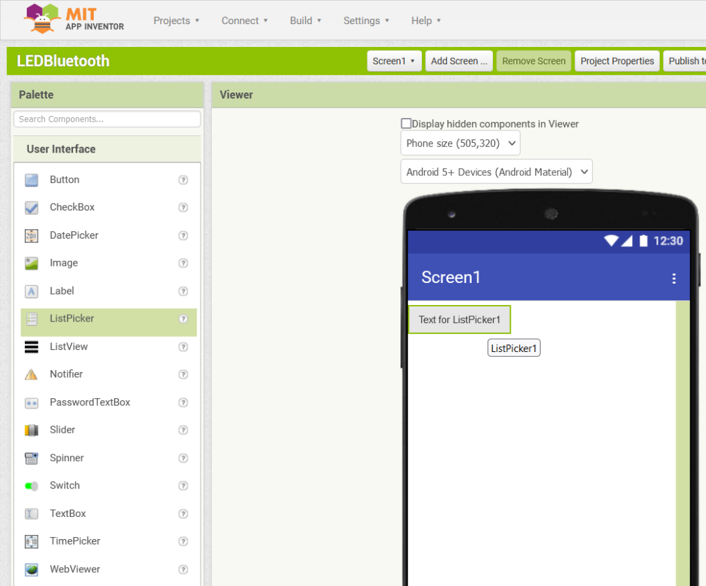
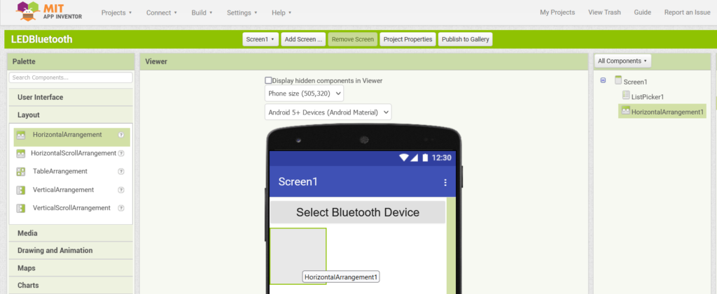
First, we must select a Bluetooth device to connect. This is provided through a ListPicker element. Select ListPicker in the 'User Interface' tab and drag and drop it to Screen1.
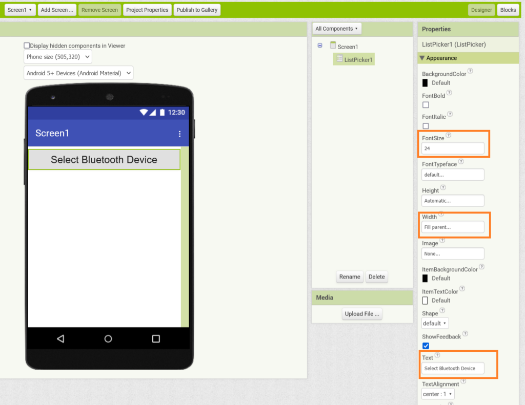
Set ListPicker's font size to 24 points, increase the width to fill the parent, and change its text to 'Select Bluetooth Device'.
Two buttons are needed to control the LED – one to turn it on and one to turn it off. These buttons can be configured in a horizontal arrangement. Select 'HorizontalArragement' in the 'Layout' tab. Drag and drop onto the screen.
Drag and drop two buttons onto the 'HorizontalArragement'.
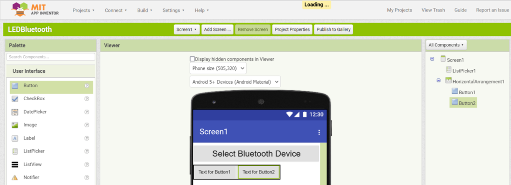
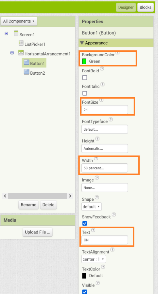
Change Button1's background color to Green, set the font size to 24 points, change the width to 50% of the parent, and change the text to 'ON'.
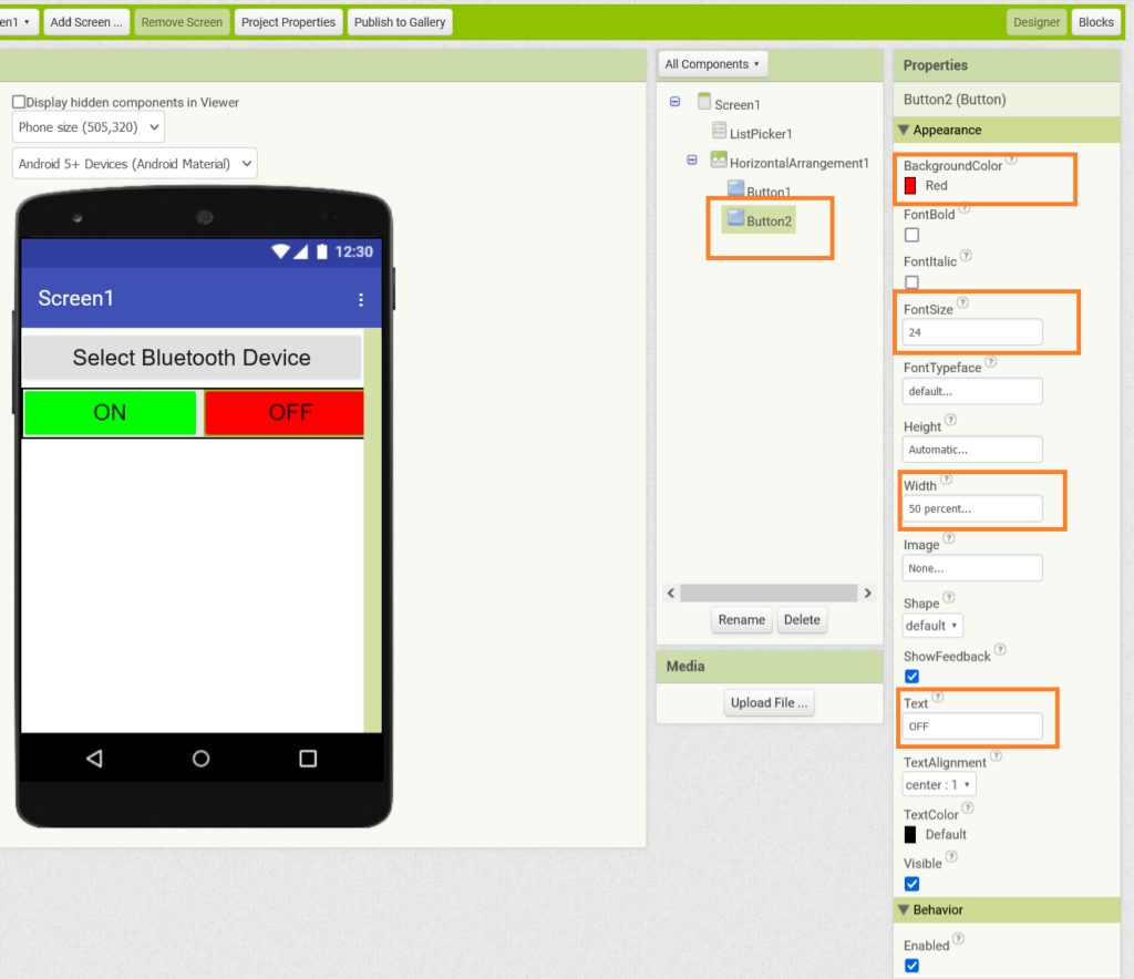
Change Button2's background color to Red, set the font size to 24 points, change the width to 50% of the parent, and change the text to 'OFF'.
We will need a Bluetooth Client on the screen to enable a Bluetooth connection. Select 'Bluetooth Client' in the 'Connectivity' tab. Drag and drop onto the screen.
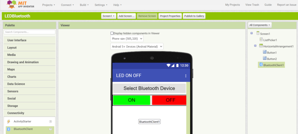
The Bluetooth Client appears as an invisible element in the user interface. This completes the user interface of our mobile app. It has a ListPicker for connecting to a Bluetooth device (i.e. Arduino) and two buttons in a horizontal arrangement for turning the LED on and off.
Now, it’s time to design our mobile app’s logic through visual programming. Click the 'Blocks' button in the top right corner. We must implement the following logic in the application.
Now it's time to design the mobile app logic through visual programming. Click the 'Blocks' button in the top right corner. It should follow this logic:
- Populate a list of available Bluetooth devices in ListPicker for user selection.
- After a user selects a Bluetooth device, the application should immediately connect to that selected Bluetooth device.
- When Button1 is clicked, the application transmits a command to turn on the LED — a data value of '1' in our case.
- When Button2 is clicked, the application transmits the command to turn off the LED — a data value of '2' in our case.
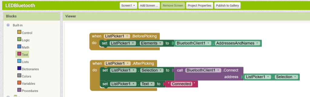
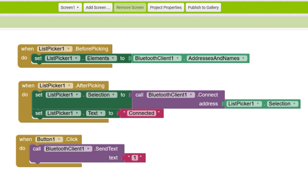
To populate the ListPicker with available Bluetooth devices, click ListPicker in the “Blocks” tab and select “When ListPicker1 BeforePicking”. Drag it into the Viewer.
Select 'Set ListPicker1.Elements To' in 'ListPicker' and drag it into the Viewer in 'When ListPicker1 BeforePicking'. Then select 'BleutoothClient1.AddressesandNames' under 'BluetoothClient1' and drag it to 'Set ListPicker1.Elements To'.

To connect to the selected Bluetooth device, drag and drop 'When ListPicker1.AfterPicking' from 'ListPicker1' into the Viewer. Drag and drop 'Set ListPicker1.selection To' from 'ListPicker1' to 'When ListPicker1.AfterPicking.' Drag and drop 'Call BluetoothClient1.Connect Address' to 'Set ListPicker1.selection To.'
To change the ListPicker test to 'Connected', drag and drop 'Set ListPicker1.Text To' to 'When ListPicker1.AfterPicking'. Drag and drop 'Text' from 'Text' to 'Set ListPicker1.Text To' and set the text to 'Connected'.
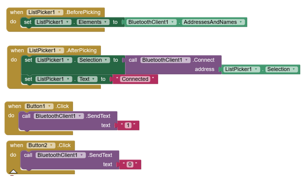
To turn on the LED when clicking Button1, drag and drop 'When Button1.click' into the Viewer. Then, drag and drop 'Call BluetoothClient.1 SendText Text' to 'When Button1.click.' Finally, drag and drop the text from 'Text' and set it to '1'.
To turn off the LED by clicking Button2, drag and drop 'When Button2.click' into the Viewer. Then, drag and drop 'Call BluetoothClient.1 SendText Text' to 'When Button2.click'. Drag and drop the text from 'Text' and set it to '0'.
This concludes the programming of our mobile application.
Testing the application
We built our device circuit, programmed the Arduino to interact with the mobile app, and completed our app using MIT App Inventor. Now it's time to test our application.
To do this, install the MIT App Companion on your smartphone. In MIT App Inventor, navigate to Connect->AI Companion. A window will appear asking you to scan a QR code or enter a code to launch the app in the MIT App Companion.
Open the MIT App Companion on your smartphone and scan the QR code or enter the code presented to launch the app.

Now you can interact with your app! First select the Bluetooth device. After connecting to the Arduino via Bluetooth, tap the 'ON' and 'OFF' buttons to ensure they work and turn the LED on and off.
The mobile app that controls the LED is demonstrated in the following video.
Conclusion
It is quite quick and easy to build mobile apps using MIT App Inventor. It is a useful platform for creating applications that can interact with electronic and IoT devices. Always start by designing your device circuit based on application requirements. Then, co-design the microcontroller firmware and mobile application based on the intended interaction between the device and the application. Have a good time!