You must have noticed token display boards in many places such as food stores, hospitals, banks, various takeaways, etc. Token display systems are used to display token numbers. Since these display boards show numeric information, they are easily designed using 7-segment LEDs. Commercial models use large 7-segment LEDs to display token numbers. It is even possible to prototype a model using Arduino.
In this project, we designed a token display system using the popular prototyping board – the Arduino and 7-segment LEDs. A token display board usually requires two or three 7-segment units. To multiplex these units IC MAX7219 is used in this project. The Arduino controls the token number setting. This system is designed to initialize token numbers to zero on startup. User can increase or decrease the number of tokens using two buttons provided as user interface. The token number can never be negative, so the token counter can never be decremented below zero.
Required components
- Arduino UNO x1
- 7 segments x3
- MAX7219 CI x1
- Press buttons x2
- Breadboard x1
- Jumper wires or connecting wires
Prerequisites
- Button interface with Arduino
- 7-segment multiplexing using MAX7219
Circuit Connections
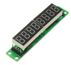
We designed a token display board here using IC MAX7219 based 7-segment driver module. MAX7219 is an 8-digit common cathode LED display driver. It allows interfacing a microcontroller with 7-segment display units of up to 8 digits. Here we use only 3 modulus digits. On the module, the data pins of the 7 segments are connected to the SEG A to SEG G and DP pins of the MAX7219. The common cathode terminals of the segments are connected to the DIG0 to DIG7 pins of the MAX7219. Pins 4 and 9 of the IC are connected to ground and pin 19 is connected to the 5V terminal. Pin 18 of the MAX7219 is also connected to 5V DC through a suitable resistor. The DIN, LOAD and CLK pins of the IC can be connected to the digital I/O pins of the Arduino.

Example of a 7-segment module based on IC MAX7219.
MAX7219 communicates with Arduino using an SPI compatible interface. The DIN, LOAD and CLK pins of the IC are connected to pins 12, 10 and 11 of the Arduino UNO. The MAX7219 module is supplied with 5V DC and Arduino's own grounding.
For user interface with token display system, 2 buttons interface with Arduino. These buttons are interfaced to pins 7 and 8 of the Arduino UNO. These Arduino pins are pulled internally. The button interfaced to pin 7 is used to increase the token number, while the button interfaced to pin 8 is used to decrease the token number.
Circuit Diagram
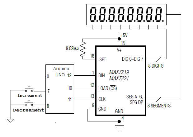
Circuit diagram of Arduino based token display system.
Arduino Sketch
How the circuit works
There are 3 7-segment LEDs connected to IC MAX7219. These 7 segments display the token number as a whole number up to hundreds places. IC MAX7219 controls the digits displayed in the 7 segments. To do this, Arduino commands are needed via the SPI interface. There are two buttons connected to the Arduino. The Arduino is programmed in such a way that pressing the button connected to pin 7 increases the token number by one. When the button connected to pin 8 is pressed, the token number decreases by one. The change in token number is immediately reflected in the 7 segments.
The code
Arduino sketching starts by importing the Arduino SPI library. Global variables are defined to assign pin numbers connected to DIN, CLK and LOAD pins of IC MAX7219. An array type variable is defined to store 16-bit commands for MAX7219. A variable is declared to store the value of the token number. The token number is an unsigned integer and is initialized to 0.
A character table is stored in the Arduino UNO's flash memory using the PROGMEM construct. This table contains the bytes that must be written to the LED segments to display the digits 0 to 9.
A spiTransfer function is defined as the shiftOut function to transfer 16-bit data to the MAX7219 IC. Each 16-bit data contains two bytes, the first byte is the address of the MAX7219 register and the second byte is the data to be written to a selected register. Both bytes are passed as arguments to this user-defined function.
A clearDisplay function is defined, in which the spiTransfer function is used to write 0x00 to all digit registers, clearing all digits. A shutdown function is defined, which uses the spiTransfer function to write data to the MAX7219 shutdown mode register.
An init_7seg function is defined to initialize the view. In the function, first, the MOSI, SCLK and CS pins are configured for digital output. The CS pin is set to HIGH to select MAX7219 on the SPI bus. A value of 0x00 is transferred to the display test register (register address 15 or 0x0F) using the spiTransfer function to set MAX7219 to normal mode. A value of 0x07 is transferred to the scan limit register (register address 11 or 0x0B), allowing all 8 digits. A value of 0x00 is transferred to the decode mode register (register address 9 or 0x09) to select no decoding for all digits.
A setChar function is defined that writes a value to a MAX7219 digit register. Both the value and the digit are defined as parameters of the function. In this function, the data of the digit numbers and the value passed are first validated. The checked value is passed to a given digit register using the spiTransfer function.
In the setup function, the init_7seg and shutdown(false) functions are called. The spiTransfer(10, 8) function is called to set the display intensity. The display is cleared by calling the clearDisplay function. The Arduino pins connected to the buttons are defined as digital input using the pinMode function.
A displayToken function is defined to retrieve the individual digits of the token number and display them in the respective 7-segment digit using the setChar function.
In the loop function, the Arduino tests the input, that is, a logical LOW in this case, from the buttons connected to pins 7 and 8. If there is input on pin 7, it increases the token number by one and displays the updated number. token number by making a call to the displayToken function. If there is input on pin 8, it decrements the token number by one and displays the updated token number by making a call to the displayToken function. Otherwise, the token number remains unchanged and is updated on the display, again making a call to the displayToken function. The loop function continues to iterate constantly, checking for updates to the user's token number and repeatedly updating the token number for the 7 threads.
Results
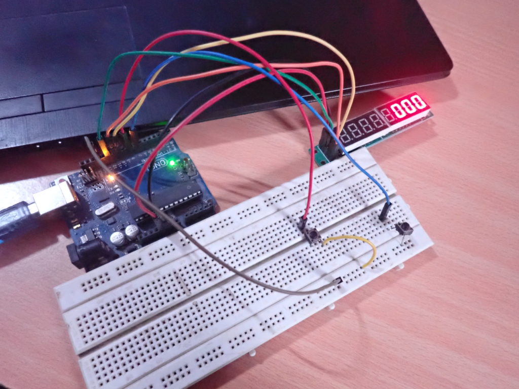
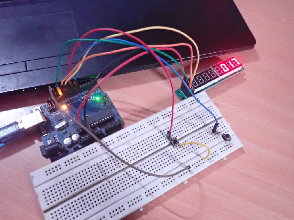 Demo video
(tagsToTranslate)Arduino