In this do-it-yourself (DIY) mini electronics project, we will design a multi-purpose level indicator that can measure various physical parameters like temperature, water, voltage, humidity, distance and more. It consists of a bar graph LED display that presents measurements.
Four main types of sensors are used to measure the different physical parameters including the following
- LM35 – detects ambient temperature
- HC SR04 (UDM) – measures the distance to an object
- Soil moisture sensor – detects soil moisture level
- Potentiometer (POT) – detects the input analog voltage level
- The bar graph LED display – indicates the different levels of physical parameters as follows:
– Temperature: 0 – 100°C
– Analog voltage: 0 – 5 V
– Distance from an object: 0 – 100 cm
– Soil moisture: 0 – 100%
Two additional LEDs indicate the maximum and minimum values of physical measurements. These LEDs flash when a sensor value reaches its maximum or minimum limit. A buzzer also beeps when maximum or sensor values are reached.
The bar graph LED displays the level of any physical parameter at a time and can be selected using the button. A user can choose any sensor by pressing the button and the sensor will display its current value on the bar graph LED.
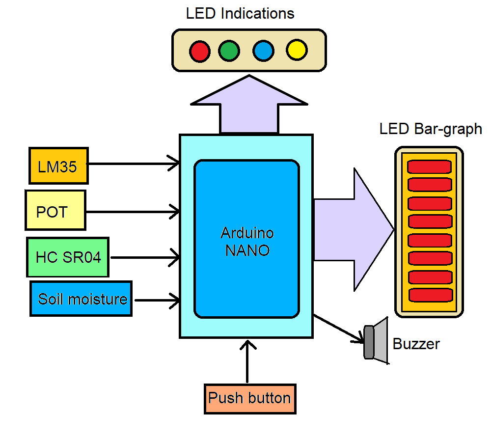
This device uses simple components including LEDs, a bar graph, a button, a buzzer, sensors, and an Arduino NANO board. Check out the block diagram below to see the configuration.
Required components
In addition to an Arduino NANO board, here's what you'll need to build this project:
LM35: a temperature sensor that measures ambient temperature and provides an analog voltage output. This semiconductor type sensor is based on the thermocouple principle. Provides calibrated output of 10 mV/o C, measuring temperature from 0 – 100° C, with 0 – 1 V output.
POT (potentiometer): a variable resistor that provides the Arduino board with analog voltage (from 0 to 5 V) as an input.
HC SR04 (Ultrasonic Distance Measurement – UDM): measures the distance between any two objects and generates a pulse width modulation (PWM) output. The width of the output pulse is proportional to the distance to the object.
Soil moisture sensor: measures soil moisture level. Conductivity varies depending on the soil moisture level. This sensor provides a 0 to 5 V output as resistance (conductivity) changes. When the soil is completely dry, the sensor resistance is at maximum and the output is 5V. When the ground is completely wet, the sensor resistance is extremely low and the output is 0 V.
LED indications: indicate the maximum or minimum level of any sensor value such as temperature, soil moisture, etc. The LEDs also indicate which sensor level is currently displayed on the bar graph.
Push Button: Used to select any sensor at a time. There are four in total. The measured level is then displayed on the LED bar graph.
Buzzer: generates an audible signal when any sensor level reaches its minimum/maximum value.
LED Bar Graph: An eight LED bar graph used to indicate the level (from 10 to 90) of the selected sensor (or parameter), such as temperature, distance, soil moisture, etc.
Arduino board: the main building block and CPU of the system. Arduino performs the following tasks:
- Reads or detects temperature, soil moisture, distance, etc., from sensors
- Provides different indications on the LEDs, such as the maximum and minimum sensor levels reached
- Generates a buzzer sound
- Displays different sensor levels on LED bar graph
- Reads user input on the button to select the correct sensor
Circuit Diagram
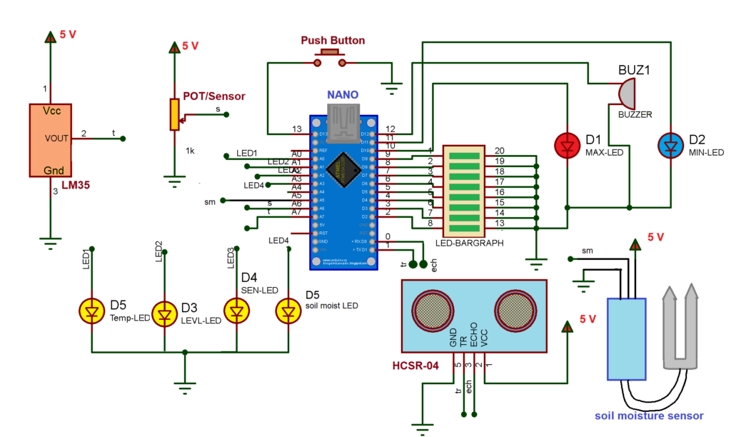
Circuit Description:
The circuit is built using an Arduino NANO board, an eight-LED bar graph display, the LM35 temperature sensor, an HC SR-04 ultrasonic distance measurement (UDM) sensor, a soil moisture sensor, some LEDs, a bell and a push button.
The LED bar graph:
- There are eight LEDs on it. All cathode terminals are shorted and connected to ground.
- Eight anode terminals are connected to the digital pins D2 – D9 of the Arduino NANO.
LED indicators:
- There are six LEDs. Its cathodes are connected to the ground.
- Max_LED (RED) is used to indicate the maximum sensor value and is connected to digital pin D10.
- MIN_LED (BLUE) is used to indicate the minimum value of the sensor and is connected to digital pin D11.
- Temp_LED (YELLOW) indicates the temperature level displayed in the bar graph. It is connected to pin A0 (digital pin 14).
- Dist_LED (YELLOW) indicates that the distance is indicated in the bar graph. It is connected to pin A1 (digital pin 15).
- SEN_LED (YELLOW) indicates the potentiometer level shown in the bar graph. It is connected to pin A2 (digital pin 16).
- Soil_most_LED (YELLOW) indicates the soil moisture level as indicated in the bar graph. It is connected to pin A3 (digital pin 17).
Buzzer: generates an audible signal when the sensor level reaches the minimum or maximum. It is connected to digital pin D12.
Push button: used to select different sensors and is connected to digital pin D13.
LM35 temperature sensor: has three pins: (1) Vcc (2) GND (3) Op. The Vcc pin is connected to 5 V and the GND pin is connected to ground. The Op pin is connected to analog input pin A7.
Soil moisture sensor: has three pins: (1) Vcc (2) GND (3) Op. The Vcc pin is connected to 5 V and the GND pin is connected to ground. The Op pin is connected to analog input pin A5.
Potentiometer: has three terminals. Two end terminals are connected to 5V and ground. The center terminal is connected to analog input pin A6.
HC SR04 UDM: has four pins: (1) Vcc (2) GND (3) Trig (4) Echo. The Vcc pin is connected to 5V and the GND pin is connected to ground. Trig and Echo pins are connected to digital pins D1 and D0 respectively.
Circuit Operation:
There are four sensors used in this circuit. Their levels are indicated on the bar graph based on the user's selection, which is performed by pressing a button. Sensors can be selected cyclically, as shown in Table I.
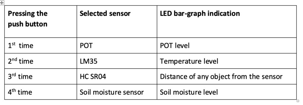
table 1
Potentiometer (POT): provides analog voltage (0 to 5 V) as input to pin A6. This analog voltage is then converted into a digital value from 0 to 1023 by the Arduino. This range is later converted into 0 to 100 and displayed in the bar graph as shown in Table 2.
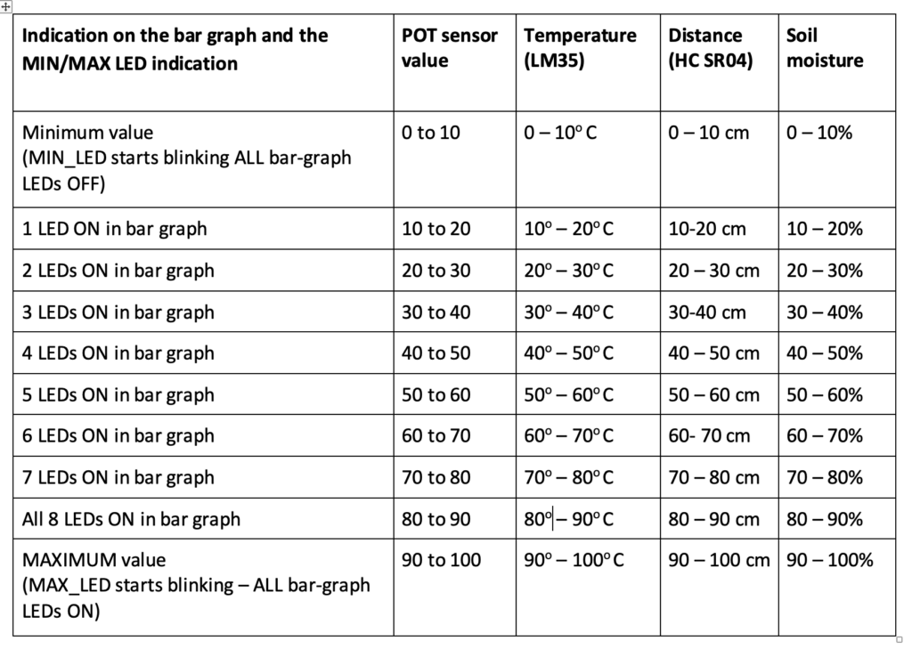
table 2
LM35 temperature sensor: measures temperature between 0 – 100° C and provides 0 to 1V analog output. It has a resolution of 10 mV/°C. Analog voltage of 0 – 1V is supplied to input pin A7. The Arduino converts this analog voltage input into a digital value in the range 0 to 100, which is displayed on the LED bar graph (as shown in Table 2).
Soil moisture sensor: measures the moisture level in the soil and provides analog voltage 0 – 5 V as output. The output is 5V when the soil is completely dry and 0V when the soil is completely wet. This analog voltage output is supplied to input pin A5, which is converted into a digital value from 0 to 1023 by Arduino. This range is later converted into 0 to 100 and displayed on the LED bar graph (as per Table 2).
HC SR-04 UDM: measures the distance to any object in front of you, generating a PWM output on the Echo pin. The Arduino measures the width of this output pulse from the Echo pin and calculates the distance to the object in centimeters. The distance to the object (between 0 – 100 cm) is displayed on the LED bar graph.
When any sensor value exceeds 90, the MAX_LED starts flashing and the buzzer beeps. Similarly, when any sensor value is less than 10, the MIN_LED starts flashing and the buzzer beeps.
The user can select:
- Temperature level
- Soil moisture level
- Object Distance
- Potentiometer level
When you press the button, the level of that sensor is displayed on the LED bar graph. It is also possible to connect with any other analog or digital sensor (such as DHT, DS18B20) and its level will be displayed. That's why this device is truly a multifunctional level indicator.