Digital compasses are electronic devices that use sensors to determine the magnetic field, numerically displaying the navigation direction.
These types of compasses typically use a magnetometer sensor to measure the strength of the magnetic field to detect direction. A low-cost three-axis digital magnetometer is the HMC5883L. It measures the value of the magnetic field along the X, Y and Z axes, ranging from milligauss to eight gausses.
The HMC5883L shares magnetic field values, in 16-bit resolution, using the I2C serial communication protocol. These values can then be used to calculate heading direction and degrees.

The HMC5833L can be easily connected to Arduino via the I2C port.
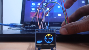
For this project, we will design a digital compass using HMC5833L and SSD1306 OLED (Organic Light Emitting Diode). The OLED display shows heading degrees and a graphic compass rose, which changes in real time.
Required components
1. Arduino Uno x1
2. HMC5833L x1
3. SSD1306 OLED x1
4. Test board
5. Connecting wires/bonding wires
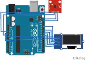
Circuit Connections
To make this digital compass, we first need to connect the HCM5833L magnetometer and SSD1306 OLED display to the Arduino Uno.
The HCM5833L breakout board has this pin configuration… 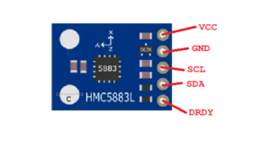
For circuit connections, connect the VCC and GND pins of the HMC5883L with the 3.3V output and GND pin of the Arduino Uno. It is important to note that the HMC5883L cannot tolerate 5V power from the Arduino and may be damaged if mistakenly connected to the 5V output. So, only use the 3.3V output.
The SCL and SDA pins of the HCM5883L must be connected to the SCL and SDA pins of the Arduino, respectively. Leave the DRDY pin on the breakout board disconnected.
The OLED display provides digital compass graphics, including heading degrees. The SSD1306 interfaces with the Arduino using its SPI physical port.
To do this, connect the D0/SCK and D1/MOSI pins of the SSD1306 OLED to the D13 and D11 pins of the Arduino, respectively. Then connect the DC, RESET and CS pins of the SSD1306 to the D9, D10 and D8 pins of the Arduino respectively.
Arduino Sketch
How the circuit works
The HMC5883L outputs magnetic field strength along three axes over the I2C protocol. The chip contains 12 integrated registers.
- The value of the magnetic field along the X axis is stored in registers 0x03 and 0x04.
- The value of the magnetic field along the Z axis is stored in registers 0x05 and 0x06.
- The value of the magnetic field along the Y axis is stored in registers 0x07 and 0x08.
- The magnetometer can be configured by programming its registers to 0x00 and 0x01.
- The compass mode can be set by programming register 0x02.
The Arduino sets registers 0x00 and 0x01 to set the gain settings to +/- 1.3 Ga. The sampling rate is kept at default 1.
Similarly, the data output rate is set to default 15, selecting the default normal measurement setting. Mode register 0x03 is configured for continuous measurement.
The Arduino reads the values from registers 0x03~0x08 and retrieves the magnetic field strengths along the three axes as 16-bit numbers. The log values obtained are in 2's complement. These raw values are converted into scaled values based on compass calibration. The scaled values are then averaged to calculate the azimuth angle or compass direction.
The Arduino also interfaces with the SSD1306 OLED as a graphical compass display. The screen shows a compass rose with an arrow in the direction. The direction obtained from the HMC5883L is displayed on the left half of the OLED screen, and the arrow indicates the same degrees on the right half of the screen.
The code
The sketch starts by importing the Adafruit_GFX.h and Adafruit_SSD1306.h libraries to work with the OLED display. The Wire.h and HMC5883L.h libraries must also be imported to work with the HMC5883L compass. The HMC5883L library can be downloaded from the Github page.
An object of class HMC5883L is instantiated and a variable defined to store the compass error. An object of the MagnetometerScaled class is instantiated to calculate the displacement along the three axes.
Then some variables are set to indicate the pin connections of the SSD1306 OLED. An object of class Adafruit_SSD1306 is instantiated, specifying the SPI protocol for proper communication with the display. Additional variables are defined to position the compass rose and direction arrow within the display screen.
The compassCalibrate function is defined for manual calibration of the HMC5883L compass. Even though the call to this function is commented out in the setup function, the compass will still work with default values for the offsets. This function is used to manually calculate displacement values with the help of Serial Monitor.
In the setup function, the baud rate for serial communication is set to 9600 bps. Serial communication is used to calibrate the compass with the Serial Monitor. The I2C port is initialized by calling the Wire.begin method.
The compass gain is set to +/-1.3 by calling the setScale method on the compass object. The measurement mode is set to a continuous measurement by calling the setMeasurementMode method on the compass object. The offset values for the three axes are calculated by calibrating the compass, which is done by calling the compassCalibrate function. The OLED display is initialized and the position of the compass rose on the screen is set.
The Draw_Compass function is defined to draw the compass rose on the OLED display. The display_direction function is defined to print directions on the compass rose. The draw_arrow function is defined to display the direction arrow inside the compass rose.
In the loop function, the raw values of the magnetic force along the X, Y, and Z axes are obtained by calling the compass.readRawAxis method. Scaled values are obtained by calling the compass.readScaledAxis method.
The scaled values are corrected by the offsets obtained during compass calibration. The tangent along the YX and ZX planes is then calculated. The degree of direction in radians is equal to the tangent of the magnetic field along the YX plane. The degree of direction is adjusted by the declination angle of the current location.
You can find the declination angle for your location at magnetic-declination.com . For my location, the declination angle is 1˚.2′. When converted to radians, this value is 0.01803.
The measured heading is set to a value between 0˚ and 360˚. The bearing value is in radians, which is converted to degrees. The OLED display is then cleared, and the heading degrees obtained are passed to the “angle” variable. This angle is displayed on the left half of the OLED screen as the heading degrees. The same angle is used to change the position direction arrow, and the compass rose and direction arrow are displayed on the right half of the OLED screen.
The result


