Light sensors are widely used in electronic applications. The most common one used is a photoresistor or light-dependent resistor. Despite a long response time, this sensor is cheap and useful in many applications.
A photoresistor consists of a zigzag track of photosensitive semiconductors. It offers pure resistance, although it depends on ambient light. If it's in the dark, the sensor has a high resistance – think several thousand ohms or mega ohms. If it is in the light, the sensor resistance drops to a few hundred ohms.
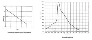
Practically, light dependent resistors (LDRs) are poor at measuring light intensity. The response of an LDR to lighting shows a sharp drop in resistance. Furthermore, its spectral response is tuned to a maximum light wavelength of 540 nm.
However, this tuning to pure green light makes the LDR particularly sensitive to the light spectrum visible to human eyes. An LDR can typically measure light or dark due to its specially tuned spectral response.

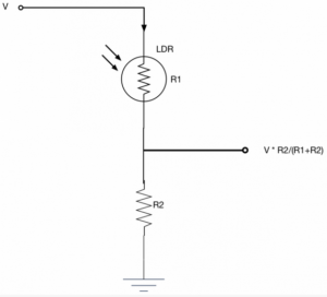
A light or dark sensor can be designed using an LDR connected to a voltage divider circuit.
Observation:
- There will be a high voltage drop across the LDR due to its high dark resistance. As a result, a low voltage will be obtained at the output of the voltage divider.
- There will be much less voltage drop across the LDR in light due to its resistance to drop in light. As a result, a higher voltage will be obtained at the output of the voltage divider.
The output of the voltage divider network is analog. The voltage divider can be paired with an operational amplifier to design the ideal light or dark sensor. First, connect the voltage divider output of the LDR resistor to the non-inverting input of an OPAMP. Apply the reference voltage to the inverting input.
- If it is dark, the LDR network output voltage will be lower than the reference voltage and the OPAMP output will be LOW.
- If it is light, the LDR network output voltage will be higher than the reference voltage and the OPAMP output will be HIGH.
Then try connecting the voltage divider output of the LDR resistor to the inverting input of an OPAMP. Apply the reference voltage to the non-inverting input.
- If it is dark, the LDR network output voltage will be lower than the reference voltage and the OPAMP output will be HIGH.
- If it is light, the LDR network output voltage will be higher than the reference voltage and the OPAMP output will be LOW.
The reference voltage can be adjusted using a potentiometer or variable resistance. Regardless of how the voltage divider network is paired with the OP-AMP, the output logic can be used to make the sensor bright or dark.
Here is a circuit diagram that can be toggled as a light and dark sensor…

This example uses an LM358 dual op amp IC. According to the above circuit, the output of the LDR resistor network is connected to the non-inverting input of one of the op-amps and inverts the input of another LM358 op-amp.
The reference voltage is adjustable via a variable resistor connected to the inverting input of the first op amp and the non-inverting input of the other. The output of the two op amps will work in opposite ways in bright or dark situations. The output of one of the operational amplifiers is drawn using jumpers. The user can choose whether to use the circuit as a light or dark sensor.
The same output can be used to drive an LED, indicating light or dark detection.
The circuit assembled on the PCB is shown here:

Interfacing an LDR with Arduino
A photoresistor can be paired with Arduino using digital or analog input. If the LDR on a voltage divider is directly interfaced with the Arduino (or any microcontroller), the network output of the voltage divider must be connected to an analog input on the Arduino.
In this case, the Arduino can be programmed to read the analog voltage from the LDR resistor network and compare it with a reference value for certain decision making – such as automatically turning on electronic lights when darkness is detected or turning off electronic lights. Automatically turns on when light is detected.

A second way to approach this is to pair the LDR resistor network with an operational amplifier (op-amp) and take the output of the op-amp to the Arduino as a digital input.
In this method, the output of the operational amplifier is physically calibrated using a potentiometer or variable resistor. This means that the user does not need to reprogram the Arduino to recalibrate the sensor when or if necessary. He or she can simply adjust the potentiometer and the recalibration is done.
Here, Arduino reads the digital logic of the LDR op amp circuit and makes the decision accordingly. This method of interfacing an LDR with Arduino is simple, easy to use, and typically preferred.
Light sensor

Dark sensor
Light and dark detection using an LDR
For this project, we will stick to the LDR sensor module so that we can select light or dark detection by placing jumpers. We will be using this module to detect light or dark and monitor the output of the LDR op-amp sensor module using Arduino Serial Monitor.
Required components
1. Arduino UNO x1
2. LDR x1
3. Resistors 330Ω x2
4. 10K resistor x1
5. 10K Pot x1
6. LM358x1
7. LEDx1
8. Breadboard x1
9. Connecting wires or jumper wires
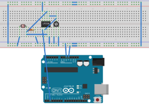
Circuit Connections
Start by connecting an LDR with a 10K resistor into a voltage divider network. Join the LDR side of the network to 5 Vdc and the resistor side of the network to ground (because the change in voltage drop must occur at the LDR).
Then connect the output of the LDR resistor network to pins 3 and 6 of IC LM358. Take a potentiometer and connect its fixed terminals to 5V DC and ground. Connect the variable terminal of the potentiometer to pins 2 and 5 of IC LM358. Pins 8 and 4 of IC LM358 must connect to VCC and ground.
To function the circuit as a light sensor, connect pin 1 of the LM358 to one of the Arduino's digital I/O pins. The circuit will output HIGH when light is detected and LOW when it is dark.
To use a dark sensor, connect pin 7 of the LM358 to one of the Arduino's digital I/O pins. As a dark sensor, the circuit will output HIGH when it is dark and LOW when there is light.
The output of the LDR op amp circuit can be used to drive an LED directly or via Arduino.
In this tutorial, the circuit has been made on a printed circuit board, on which operation as a light or dark sensor can be selected using a jumper connector or a 2-pin shunt. An LED is already provided on the PCB to indicate light or dark detection.
Therefore, the output of the LDR op amp circuit is connected to the analog input pin A0 to monitor the change in the op amp output voltage depending on whether there is light or dark.
Arduino Sketch
const int ldrPin = A0;
empty configuration {
Serial.begin(9600);
pinMode(ldrPin, INPUT);
}
empty loop {
int ldrStatus = analogRead(ldrPin);
Serial.println(ldrStatus);
delay(1000);
}
How the circuit works
The output of the LDR resistor network is connected to the non-inverting input of one of the operational amplifiers and inverts the input of another LM358 operational amplifier. The same reference voltage is applied to the opposite inputs of both operational amplifiers. This reference voltage is calibrated by the user.
If it is dark, the LDR provides high resistance in the circuit. Due to the high resistance, there is a high voltage drop across it. As a result, a voltage lower than the reference voltage is output from the voltage divider network. This also means that the output on pin 1 of the LM358 is LOW, while pin 7 is HIGH.
When there is light, the resistance of the LDR drops to a few hundred ohms. Due to the drop in resistance, there is a low voltage drop across the LDR. As a result, a voltage greater than the reference voltage is output from the voltage divider network. Therefore, the output on pin 1 of the LM358 is HIGH while pin 7 is LOW.
The result


(tagsToTranslate)Arduino