Laser Plate Cutting Machine Troubleshooting
1.1. The cut has sharp corners Solution steps
Solution steps (if the previous step is ineffective, proceed to the next step):
- Compensate reverse slack (change in platform configuration);
- Check gear and rack engagement;
- Inspect the engine installation, make sure that the spacer installation is correct and that the couplings are tight;
- Check that the slide screws are securely tightened.
1.2. Corrugated cutting problem
Solution steps (if the previous step is ineffective, proceed to the next step):
- Press the material manually while cutting and observe the cutting effect;
- Check for instability or oscillation in the levelers and machine table structure; do not use unstable or unreliable profiles under the pads;
- Adjust cutting parameters;
The. Reduce the following sensitivity in the software settings;
B. Increase vibration suppression in software settings;
w. Adjust servo parameters; - Compensate reverse slack (change in platform configuration);
- Check if the cylinder locks the gearshift platform;
- Make sure the laser head and related components are firmly fixed;
- Inspect the engine installation, make sure that the spacer installation is correct and that the couplings are tight;
- Check that the slider screws are tight;
- Check the engagement of the X and Y axes, requiring 0.06-0.08mm;
- Replace the X and Y reduction gears and motors.
1.3 Low cutting precision
Solution steps (if the previous step is ineffective, proceed to the next):
- Make sure the laser head and related components are firmly fixed;
- Adjust process parameters and servo parameters;
- Compensate reverse slack (change in platform configuration);
- Check the engagement of the X and Y axes, requiring 0.06-0.08mm;
- Check the verticality of the X and Y axes, 0.03mm;
- Inspect the engine installation, make sure that the spacer installation is correct and that the couplings are tight;
- Check that the slider screws are tight;
- Use a laser interferometer.
1.4 Abnormal noise problems
Solution steps (if the previous step is ineffective, proceed to the next):
- Check the location of the abnormal noise, and if it is caused by sheet metal parts or dust cloth, trim the sheet metal parts and dust cloth;
- Z axis noise:
The. Check the leveling of the laser head fixing plate, replace if necessary;
B. Check the center height of both ends of the screw and the coaxiality of the nut seat, adjust with copper shims if necessary;
w. Inspect the couplings and make sure they are tight;
d. Check the motor, adjust the parameters, inspect the brake circuit until replacing the motor and servo. - X-axis noise:
The. Check the rack engagement gap: 0.06-0.08 mm;
B. Use a rack gauge to check the parallelism between the rack and the guide rail on the same side, ≤ 0.03mm/1000mm;
w. Check the levelness of the machine head installation with the slider, requiring an error of 0.03mm; replace the machine head if the error exceeds 0.2 mm;
d. Check the parallelism of the guide rails, the straightness of the guide rail should be ≤0.02mm/1000mm, after installation, make sure the guide rail is in close contact with the bearing surface, use a 0.02mm feeler gauge to detect, and the feeler gauge should not type;
It is. Check the motor, adjust the parameters until replacing the motor and servo; f. Replace the slider. - Y-axis noise:
The. Check the rack engagement gap: 0.06-0.08 mm;
B. Use a rack gauge to check the parallelism between the rack and the guide rail on the same side, ≤ 0.03mm/1000mm;
w. Check the flatness of the beam installation with the cursor, an error of 0.03mm is required; replace the beam if the error exceeds 0.2 mm;
d. Check the parallelism of the guide rails, the straightness of the guide rail should be ≤0.02mm/1000mm, after installation, make sure the guide rail is in close contact with the bearing surface, use a 0.02mm feeler gauge to detect, and the feeler gauge should not type;
It is. Check the motor, adjust the parameters until replacing the motor and servo; f. Replace the slider. - For abnormal noises coming from peripheral accessories such as water cooler fans, replace them directly.
1.5 Diagonal discrepancy
Solution steps (if the previous step is ineffective, proceed to the next):
- Check which direction presents a problem in the dimensions of the X and Y axes; the error for both the 500 mm side length and the diagonal should not exceed 0.1 mm;
- Compensate reverse slack (change in platform configuration);
- Adjust the diagonal compensation parameter;
- Check the engagement of the X and Y axes, requiring 0.06-0.08mm;
- Check the verticality of the X and Y axes, 0.03mm; If the accuracy is satisfactory, adjust the verticality according to the actual diagonal deviation.
1.6 Stopping movement of the X axis, Y axis and Z axis
Solution steps (if the previous step is ineffective, proceed to the next):
- Adjust engine drive parameters;
- Inspect the engine installation, make sure that the spacer installation is correct and that the couplings are tight;
- Replace the engine if there are problems with the engine itself;
- Check the motor, adjust the parameters, inspect the brake circuit until replacing the motor and servo.
1.7 Clipping effect problems
Solution steps:
Structural Steel: Cutting with O 2
| Defects | Possible Causes | Solutions |
| No burrs, consistent entry lines |
Adequate powerAdequate cutting speed | |
| Significant shift from lower entry line, wider undercut |
Cutting speed too high Cutting power too low Gas pressure too low Focus too high | Decrease cutting speed Increase cutting power Increase gas pressure Decrease focus |
| Slag-like bottom burrs, forming droplets and easy to remove |
Cutting speed too high Gas pressure too low Focus too high | Decrease cutting speed Increase gas pressure Decrease focus |
| Connected metal burrs can be removed as a whole piece |
Very high focus | Lower the focus |
| Metal burrs on the bottom surface are difficult to remove |
Cutting speed too high Gas pressure too low Impure gas Focus too high | Decrease cutting speed Increase gas pressure Use purer gas Decrease focus |
| Burrs on one side only |
Incorrect laser coaxial alignment Nozzle orifice defect | Adjust laser coaxial alignment Replace nozzle |
Material ejected from the top 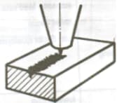
|
Power too lowCutting speed too high | Increase powerDecrease cutting speed |
| Cutting surface does not need |
Gas pressure too high Damaged nozzle Nozzle diameter too large Poor quality material | Decrease gas pressureReplace nozzleInstall appropriate nozzleUse materials with smooth, even surfaces |
Stainless steel: High pressure N 2 cutting
| Defects | Possible Causes | Solutions |
| Producing small, regular teardrop-shaped burrs |
Focus too lowCutting speed too high | Increase focusDecrease cutting speed |
Long, irregular filament-like burrs on both sides and extensive discoloration of the board surface 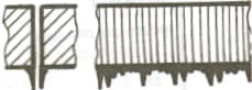
|
Cutting speed too lowFocus too highGas pressure too lowMaterial too hot | Increase cutting speed Decrease focus Increase gas pressure Cool material |
Long, irregular burrs on only one side of the cutting edge 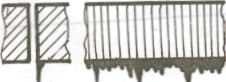
|
Incorrect laser coaxial alignmentFocus too highGas pressure too lowSpeed too low | Adjust laser coaxial alignmentDecrease focusIncrease gas pressureIncrease speed |
| The cutting edge turns yellow | Oxygen impurities in nitrogen gas | Use high quality nitrogen gas |
| Divergent beam at starting point | Acceleration too high Focus too low Melted material not ejected correctly | Decrease acceleration Increase focus Drill round holes |
| Rough cut | Damaged nozzle Dirty lens | Replace the nozzleClean the lens and replace if necessary |
Material ejected from the top 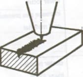
|
Power too low Cutting speed too high Gas pressure too high | Increase powerDecrease cutting speedReduce gas pressure |
1.8 Component interference problem
Solution steps (proceed to the next step if the previous one is ineffective):
First, make a judgment call, consult quality control inspectors, review drawings, if the component does not match the drawing, return it to the warehouse and replace it with a qualified component. If it matches the drawing, consult technical support personnel to check the drawing and provide a specific solution. List of possible solutions:
- If there is interference with the E series shift platform gearboxes, cut off the interfering part if it does not affect the appearance.
- If there is interference between the E series gearbox and the dust cloth, install spacers in the lower mounting holes to move the gearbox out.
- If the PT series Y-axis drag chain seat is an older version, re-drill the mounting holes.
- If the drag chain seat box on the PT series Y-axis drag chain seat interferes with the platform during movement, modify the direction of the installation hole in the cross beam to angle the drag chain.
- If the sliding door of the large PT cabinet operates abnormally and is not flush with other panels, install spacers. …….
1.9 Installation issues
Solution steps:
- Carefully review 3D assembly or subassembly drawings.
- Review the assembly process.
- If there are no technical documents, contact technical support personnel.
1.10 Interference problems
Solution steps:
- Black screen on display: First, check if the ground wire is connected correctly, shielded cables are used, test with added ferrite beads and try to replace the industrial computer.
- Distorted display with snowflakes on the screen: This problem occurs more frequently on Series I machines. Check whether the ferrite beads are installed in the VGA cable, separate the main circuit from the servo driver and the VGA cable, and avoid placing them in the same cable tray.
- Poor calibration results for tube machines: There must be a connecting plate between the tube bed and the plate bed, and the equipment must be properly grounded.
1.11 Chiller alarm
Solution steps (proceed to the next step if the previous one is ineffective):
- Check the refrigerator screen for alarm information: Common alarms include low liquid level, flow rate, and temperature alarms. For low liquid level, add water; for flow alarms, check piping for blockages or leaks and inspect chiller frequency; For temperature alarms, check ambient temperature, filter blockage, and possible damage to the temperature sensor.
- Determine whether it is a wiring issue or a software configuration issue based on the status of the adapter card entry point.
- Check for incorrect wiring (normally open or normally closed).
- Review chiller alarm settings in platform configuration.
1.12 Z axis limit alarm
Solution steps (proceed to the next step if the previous one is ineffective):
- Determine whether it is a wiring issue or a software configuration issue based on the status of the adapter card entry point.
- Check for incorrect wiring.
- Review the threshold settings in the platform configuration.
- Replace the limit switch.
1.13 Driver alarm
Solution steps:
- A.710, A.910 and A.720 Overload: Check that the three-phase sequence is correct, that the parameter settings are correct, that any wires are disconnected and that the mechanical transmission is working correctly.
- A.F10 Line phase loss: Check if parameter Pn00B is set to single-phase or three-phase and if any motor supply line is disconnected.
- Excessive position deviation A.900: Shut down and restart, initialize the driver and reset the parameters, and check whether the mechanical transmission is stuck or the backlash is too large.
- A.840 encoder data alarm: Encoder malfunction, restart the power supply, check whether the encoder wiring is good and the shielded cable is properly grounded.
- Driver quality failure, replace the driver.
1.14 Shooting problem
Solution steps:
- Check the main circuit for short circuits or grounded wires.
- Check the driver power line for short circuits or ground.
1.15 Error in cutting software
- Uninstall and reinstall the hacking software.
- Switch to a lower or higher version of the software.
1.16 Wiring error
- Check the circuit according to the electrical schematic diagram.
- Use a multimeter to test the cable for continuity and apply the elimination method to find the source of the fault.
Laser Tube Cutting Machine Troubleshooting
2.1 Low cutting accuracy with manual chuck
Solution steps (proceed to the next step if the previous one is ineffective):
- Check the verticality of the adjustment screw hole in the front jaws of the chuck; replace the part if the verticality is not satisfactory.
- Check whether the coaxiality of the front and rear chucks is ≤0.15.
- Ensure components are securely connected according to screw tightening torque requirements. Method: Attach a dial indicator to the rear chuck while the front chuck remains stationary and rotate the rear chuck. Check your coaxiality. If the coaxiality is not satisfactory, adjust the front chuck up, down, left, or right until the coaxiality meets the standard.
2.2 Low cutting accuracy with electric chuck
Solution steps (proceed to the next step if the previous one is ineffective):
- Verify that the precision tube being cut is standard, with tube precision based on class GB-17395-1988-E3 and a total length bending class of 0.1%. Replace the tube if it is not standard.
- Check that the fixation of the pipe material is correct.
- Check axial movement at the front chuck screw. If there is axial movement, eliminate it by adding shims to the screw support bearing.
- Check movement in the front jaws of the chuck along the Y axis of the machine tool. If there is movement, replace the locking sleeve.
- Check the parallelism and verticality of the front chuck jaws. Method: Use a rectangular aluminum tube, clamp the rear chuck, and leave a gap between the front chuck jaws and the rectangular tube. The gap in all four directions must be uniform at ≤±0.05. Use the rectangular tube to assess the parallelism and verticality of the jaws, observing the distance between them. If the jaws are not parallel and vertical, adjust the front chuck jaws.
- Check that the rear chuck jaws are securely clamped. If there is any loosening, tighten the loose screws.
- Check the circularity and repeatability positioning accuracy of the front and rear jaws of the chuck, with
 ≤0.15. If the circularity and repeatability positioning accuracy are out of tolerance, adjust the front and rear jaws of the chuck. When checking with the dial indicator, record the maximum eccentricity position and adjust the jaw inward to the maximum position. When adjusting the jaws, try adjusting just one side.
 - If all of the above factors have been verified and there are no problems, inspect the coaxiality of the front and rear chucks. The coaxiality of the front and rear chucks should be ≤0.08. Method: Attach a dial indicator to the rear chuck and measure the inner circle and end face of the front chuck. Observe the offset values on the dial indicator to determine the coaxiality and end face offset of the front and rear chucks. If the end face coaxiality and eccentricity values are out of tolerance, adjust the front chuck left, right, up, or down until the end face coaxiality and eccentricity meet the standard.
- Replace the chuck.
2.3 The initial cutoff points do not coincide
Solution steps (proceed to the next step if the previous one is ineffective):
- Check whether the front chuck current value is too high.
- Check the coaxiality of the front and rear chucks if they are on different axes; must be ≤0.15.
- Check the eccentricity value of the chuck front face with
 ≤0.1. Method: Attach a dial indicator to the rear chuck and measure the inner circle and end face of the front chuck. Observe the offset values on the dial indicator to determine the coaxiality and end face offset of the front and rear chucks. If the end face coaxiality and eccentricity values are out of tolerance, adjust the front chuck left, right, up, or down until the end face coaxiality and eccentricity meet the standard.
 - Check whether the rear chuck spindle has axial movement.
2.4 Corrugated cutting problem
See Chapter 1, Pipe Cutting Machine Problem 1.2.
2.5 Large edge location error
Solution steps (proceed to the next step if the previous one is ineffective):
- Check that the laser head is vertical; Replace the laser head connection plate if it is not vertical.
- Eliminate interference caused by current in the front and rear chucks by connecting them to the machine base with copper wires.
2.6 Interference problem
See Chapter 1, Sheet Cutting Machine Problem 1.10.
2.7 Water cooling machine alarm
See Chapter 1, Sheet Cutting Machine Problem 1.11.
2.8 Z axis limit alarm
See Chapter 1, Sheet Cutting Machine Problem 1.12.
2.9 Driver alarm
See Chapter 1, Sheet Cutting Machine Problem 1.13.
2.10 Stumbling problem
See Chapter 1, Sheet Cutting Machine Problem 1.14.
2.11 Error in cutting software
See Chapter 1, Sheet Cutting Machine Problem 1.15.
2.12 Wiring error
See Chapter 1, Sheet Cutting Machine Problem 1.16.
High Power Laser Cutting Troubleshooting
1. High-power laser cutting market situation
With the evolution of the laser industry and the changing demands of the downstream industry, high-power laser cutting equipment has gradually become a focal point of market interest.
With incomparable advantages in speed and thickness, high-power laser cutting has won wide recognition in the market.
However, as high-power laser cutting technology is still in the early stages of widespread adoption, some operators are not fully proficient in managing this cutting process and are often lost when they face problems during production debugging.
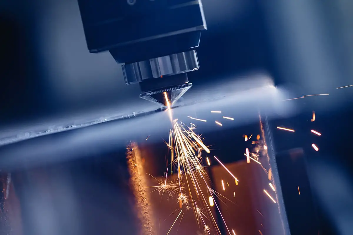
To resolve these issues in high-power cutting, cutting process technicians offer some troubleshooting tips to help you adjust the correct laser cutting process parameters (Figure 1).
This will not only reduce losses caused by defective parts, but also increase your cost-benefit ratio from another perspective.
2. Elimination of Defects
There are many reasons why high-power lasers can produce defective parts during the cutting process. The main problems can be diagnosed from the following four aspects.
(1) Basic troubleshooting
If unsatisfactory cutting results are detected, first check the following problems:
1. Are the lenses contaminated?
2. Is the nozzle damaged?
3. Is the light centered on the nozzle?
4. Are there any leaks or damage to the ceramic body?
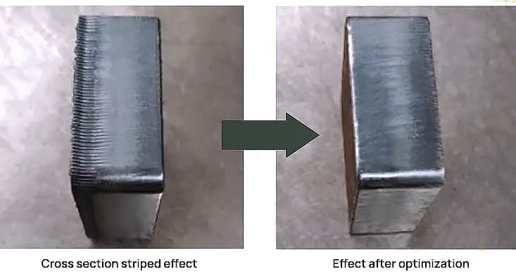
(2) Methods for eliminating sectional stripes
1. Possible reasons:
Incorrect nozzle selection – nozzle too large; incorrect air pressure setting – excessive burning with streaks due to too high pressure; incorrect cutting speed – excessive burning caused by too slow or too fast a speed.
2. Solutions:
Change the nozzle, opt for a smaller diameter nozzle, for example, a D1.4 high-speed nozzle for bright cutting of 16mm carbon steel, and a D1.6 high-speed nozzle for bright cutting of 20mm carbon steel; reduce cutting air pressure to improve the quality of the cut section; Adjust the cutting speed so that the power matches the cutting speed to obtain the effect shown in Figure 2.
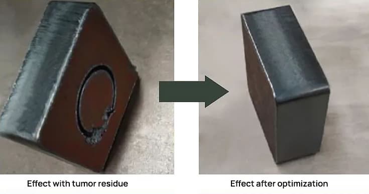
(3) Methods for eliminating bottom slag
1. Possible causes:
The nozzle used may be too small, the cutting focus may be incompatible; air pressure too low or too high, cutting speed too fast; poor quality of plate material, poor quality plate, small nozzles have difficulty removing slag.
2. Solutions:
Replace with a larger diameter nozzle, adjust the focus to the appropriate position; increase or decrease air pressure until airflow is adequate; Choose good quality board material. This can achieve the effect shown in Figure 3.
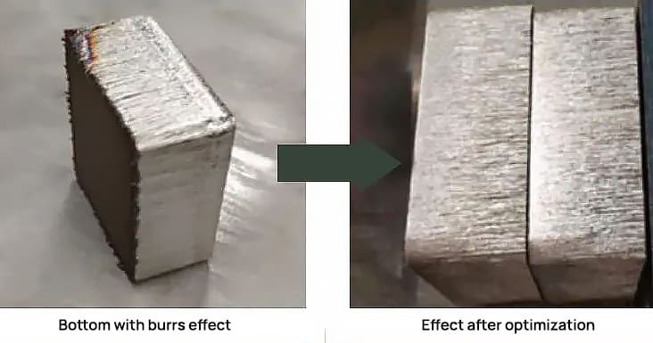
(4) Methods for eliminating lower burrs
1. Possible causes:
The nozzle diameter is too small to meet machining requirements; negative blur is incompatible and must be increased and adjusted to the appropriate position; the air pressure is too low, resulting in burrs at the bottom and insufficient cutting.
2. Solutions:
Use a larger diameter nozzle to increase airflow; increase the negative blur to allow the cropping section to reach the bottom position; increase air pressure to reduce bottom burrs. This can achieve the effect shown in Figure 4.
3. How to determine whether the cutting speed is appropriate according to the sparks
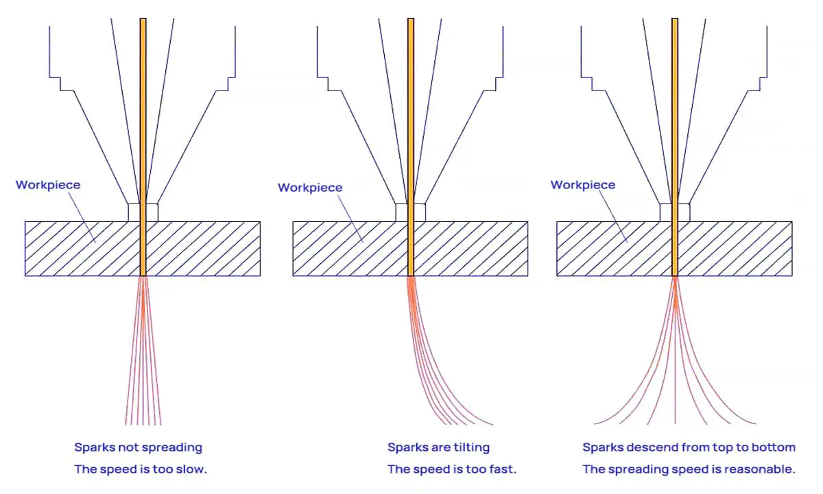
(1) Appropriate cutting speed: Cutting sparks diffuse downwards, resulting in a smooth cutting surface with no debris on the bottom.
(2) Excessive cutting speed: Cutting sparks skew.
(3) Insufficient cutting speed: The cutting sparks do not diffuse and are few and grouped together.
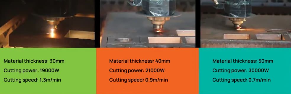
In response to these questions, the power of the laser cutting machine (see Figure 6) is compatible with the 20,000 to 30,000 watts most commonly used in the current sheet metal processing market. With bilateral servo motors, it offers fast speeds, precise positioning and smooth operation.

4. Conclusion
High cutting speed is a significant advantage of laser cutting and the main reason why many sheet metal processing users choose laser cutters. However, faster is not always better. Only by controlling the appropriate cutting speed can a smooth, slag-free cutting surface and high-quality workpieces be achieved.
Laser power affects the speed at which the laser equipment cuts the sheet metal, and this cutting speed, in turn, affects the quality of the sheet metal cut. Under fixed laser power, there is an optimal range of cutting speeds. Speeds that are too fast or too slow can negatively affect the smoothness of the cutting cross section.
Other 63 Laser Cutting Machine Troubleshooting Guide
Laser cutting machines often malfunction during use. Without professional guidance, it can be difficult to accurately determine the source of the problem with your laser cutting equipment. We can only rely on our own experience to figure this out.
However, when some problems arise for the first time, we may feel lost and even have difficulty describing the problem clearly when consulting the manufacturer's after-sales support.
To help you, I have carefully selected some common problems in laser cutting machines and their corresponding sources or solutions.
1. Poor cutting quality or inability to cut?
Potential causes include low power settings, small potentiometer adjustments, misaligned optics, dirty lenses, improperly installed focusing lenses, focal length problems, laser power supply problems, laser tube power attenuation, high temperature of the water and unstable voltage. Address these questions step by step based on the actual situation.
2. Unable to connect to the device?
Check whether the card drivers are installed, whether the USB or Ethernet cables are connected correctly, whether the cables are damaged, whether the adapter card is defective, and other card-related issues.
3. Does the machine return to the wrong origin when turned on?
The original key may be defective.
4. Deformation of cutting shape and overlapping cuts?
Possible causes include loose synchronous wheel bolts, broken motor wires, faulty motor, driver problems, and voltage problems.
5. The device does not start and the internal circuit breaker trips when turned on?
Check that the emergency stop button is released, that the external circuit is connected, that the device's internal circuit breaker is closed and that you hear a “pop” sound when turning on. In this case, inspect the main contactor and control transformer.
Also, check the water protection system for water leakage, causing a short circuit in the laser power supply (e.g. JGHY12570 water protection installed on the side of the laser power supply just below), a short -circuit in water pump 107 or the use of an undersized internal circuit breaker.
6. High voltage electric arc?
This issue can be quite troublesome. It is recommended to add a high voltage insulating sleeve over the high voltage wire.
7. Crop the chart size too big or too small?
Check whether the output graph size is consistent, whether there are changes in the Z-axis height position, and whether the calibration files require adjustments.
8. Different colors in the center and around the cropped image?
Adjust the focusing coefficient and W-axis focusing point.
9. Damaged marks or rough spots during marking?
Check dynamics and DA board.
10. Graphical position offset marking?
Check the displacement of the X or Y axis on the scanning mirror, find the center point, and adjust the position of the XY axis according to the actual direction of displacement.
11. Does the XY axis of the scanning mirror oscillate randomly when turned on and does the dynamic motor make abnormal noises?
Replace the ±12±15V switch power supply; Replace the ±12±28V switch power supply.
12. No laser output?
Check whether the chiller return water flow is normal, whether there are changes in the W axis position, whether the DC48V32A laser power supply is working properly, and other problems related to the laser tube.
13. There is no display on the control panel when turned on?
Check whether the 5V12V24V switch power supply is working properly and inspect the display panel.
14. Does the control panel malfunction and the machine does not return to its origin when turned on?
Replace the offline control board.
15. Does the Z axis not feed material or move weakly?
Possible causes include problems with the Z-axis feed motor, driver problems, bearings, or foreign objects causing obstruction.
16. Does the glass tube not emit light?
The glass tube output control mainly includes the laser tube, laser power supply, water circulation system and output signal. The output signal consists of the control board PWM output signal, the water protection signal and the door switch signal.
If the laser tube does not emit light, focus on the laser tube, laser power supply, water circulation system and output signal.
First, check whether the laser power supply is working normally, whether there are any abnormalities in the inner and outer tubes of the laser tube, and whether the water circulation system is normal.
If not, replace or adjust accordingly. If everything is normal, consider the exit signal.
First, test the laser tube and laser power supply using the short circuit signal method. If it works, there is no problem with the laser tube or laser power supply, and the problem is with the water protection switch, relay, door switch, or control card PWM signal.
If this method fails, the problem is with the laser tube or laser power supply, and you can use the replacement method to solve the problem.
17. Does the RF laser tube not emit light?
Make sure the water circulation is clear and the laser power supply starts normally.
First, test whether the 48 VDC voltage of the laser power supply is normal. Check the conductivity of pins 4 and 13 of the laser tube's 25-pin connector; conductivity indicates that the water protection signal is normal. If not, check the water protection.
Test the voltage between pins 7 and 20; a DC voltage of 4-5 V when not pressing preset or start and 1-3 V when pressing preset or start indicates a normal signal (low level conduction).
If the water, power supply and these two signals are normal, it is generally a problem with the laser tube. If the signals are abnormal, it indicates a problem with the control board or circuit.
18. Does RF laser tube replacement show “laser tube connection error”?
If the connector (internal wires are not desoldered or short-circuited), power supply wires (left positive, right negative and ground connected to the negative terminal) and water connections are normal and the device still cannot turn on connect correctly after restarting the chiller and equipment, it is usually a problem with the 25-pin connector connection circuit board or incompatibility, such as encrypted and unencrypted tubes not being compatible with the circuit board.
19. Does the cutting machine make misaligned cuts?
(Overcropped or collinear graphs cropped with great distance)
1.) Feeding misaligned cuts:
- a) Check the feed shaft pitch; pitch = measured length * original pitch / actual length (defined feed length).
- b) Check whether the power shaft synchronous belt clamping wheel and the motor synchronous belt clamping wheel are loose.
- c) Check whether the roller mesh is loose and whether there is relative slippage between it and the feed shaft or whether there is any locking phenomenon.
2.) Misaligned cuts that don’t feed:
- a) Check whether the large trolley motor or optical axis synchronous wheel is loose.
- b) Check for step loss phenomena, which may be caused by too high processing speed, idling speed or acceleration, poor motor wire contact, too low driver current, or faulty driver or motor. Engine failure that causes loss of steps is relatively rare.
20. Long feeding into the feeding machine?
If the feeding machine feeds for a long time, it is generally due to a malfunction of the photoelectric switch or incorrect sensitivity of the photoelectric switch to light. The light sensitivity of the photoelectric switch can be adjusted.
When the upper and lower switches are lit simultaneously while the feeding machine is running, the feeding machine will start.
If the light sensitivity is too high, the machine will detect light even when the cutting material is blocking it, causing overfeeding. In this case, adjust the sensitivity knob on the photoelectric switch wiring until the indicator light turns on when material is blocking it.
21. Coarse light spot on galvanometer machine?
If the light intensity is not sufficient and the basic optical path and the beam expander optical path have been adjusted well, and the dynamic focal length has been adjusted well, but the light spot is still coarse, it will be necessary to adjust the distance between the two beam expander lenses.
For our commonly used 3x beam expander, adjusting the output beam spot diameter to 13-14mm generally provides good results. You can also adjust it according to the customer's processing requirements.
22. Galvanometer machine with dynamic self-excitation?
For Shanghai Dynamics, adjust R103 and R28 to regulate self-excitation and howling. If the adjustment is ineffective, measure whether the motor shaft is short-circuited to the machine housing. During measurement, disconnect the motor power wire; otherwise it will be continuously conductive.
If it still continues driving after disconnecting the engine power wire, use an insulation film to insulate the engine and machine housing, and then adjust R103 and R28 again. If it is still ineffective after solving these problems, replace the components.
23. Incorrect marking or cutting size on marking and cutting machines?
For dynamic marking machines, incorrect size without moving the galvanometer lens up and down is generally due to changed or incorrect calibration parameter data. Recalibrating the galvanometer parameters may solve the problem.
For cutting machines, incorrect cut sizes are often caused by errors in step distance and driver pulse count. Generally, determining the pulse count and calculating the step distance can solve the problem.
24. Does the cutting machine reverse direction from the initial position when turned on?
This type of malfunction is usually caused by a damaged home position switch. There are two types of home position switches: proximity switches and reed switches (magnetic control switches). The reverse direction from the home position is generally caused by a short circuit in the switch coil. Replacing the key may solve the problem.
25. Failure of cutting machine motor, motor driver, motor wire and driver DC power supply switch?
Specific manifestations of such equipment failures are generally:
(1) The laser head does not move
(2) The movement of the laser head is abnormal, with pauses or oscillations during operation. In such cases, first observe and measure whether the 48 V or 42 V DC switching power supply is working properly.
Insufficient or unstable supply voltage can cause these phenomena. If the switching power supply operates normally, consider whether the fault is in the driver, motor, or motor wire.
To determine if the motor is defective, first check that the motor itself rotates smoothly without power and with the motor wire disconnected from the driver. If the engine rotation is abnormal, it can be directly determined as an engine failure and replaced. If the engine runs normally, measure the engine coil.
For a six-wire motor, AC, A+ and A- form a group of coils; AC and A+ and A- must be conductors. BC, B+ and B- form another group of coils, with the same conductivity situation. If the conductivity is abnormal, it can be directly determined as an engine failure.
For Baishan and YAKO stepper drivers, if the DC power supply is normal and the motor wire is disconnected and the driver indicator light is off, it can be directly determined as a driver failure. If you cannot directly determine the failure, you can use the replacement method for testing.
Failures in the motor wires are low probability problems in this type of failure. If the motor and driver have been discarded, the motor wire must be considered. Check for shorts and open circuits, and use a multimeter for detailed continuity testing to troubleshoot problems.
26. Does the laser tube not emit light?
- The water level switch is broken.
- The high voltage line is disconnected.
- The laser tube is cracked or burned.
- The laser power supply is damaged.
- No water circulation (including blocked water pipes and non-working water pump).
- The water protection wire is disconnected or has poor contact.
- No 220V input for laser power supply.
- No signal input to laser power supply (broken signal wire or poor contact, damaged control relay, damaged circuit board or poor soldering).
- The two-axis plate is broken.
27. Does the laser tube emit weak light?
- Damaged laser tube or burned lens.
- Decay of light from the laser tube.
- Damaged component in the laser power supply.
- The set laser power is too low.
- Power regulator not set to maximum.
28. Can't cut?
- Weak laser power.
- Dirty or damaged laser lens.
- Loose or incorrectly installed laser lens.
- Incorrect focal length.
- Beam misalignment.
- The set laser power is too low.
- Irregular work table.
29. Can't turn on the machine?
- The machine is not turned on.
- The air switch tripped.
- The emergency stop switch is pressed.
- The start button is broken.
- The 24 V transformer is damaged.
- The contactor is damaged.
- Broken wire.
- Poor wire contact.
30. The 24V switch power supply is broken; machine X, the Y axis cannot move?
- The 42V switch power supply is damaged.
- The circuit board is damaged.
- Problems with signal wire.
31. Is the machine on the X-axis or Y-axis not moving or not powered?
- No power supply for the driver.
- The driver is damaged.
- Bad contact or broken wire in the driver.
- The engine plug is damaged or has poor contact.
- The motor shaft is broken.
- The drive belt is loose or broken.
- Problems with the driver signal wire.
- The slider or drive wheel is stuck.
32. Machine cutting misalignment
- The belt is loose.
- The machine wheel bolts are loose.
- Damaged machine driver.
- Broken or damaged machine wire.
- Machine motor plug damaged or poor contact.
- Engine problems.
33. Can't detect the control card when connected to the machine?
- Damaged card.
- The card is not inserted correctly.
- The computer plug is damaged.
- The DPIO module driver is not installed.
34. The camera cut is inaccurate
- Calibration not performed.
- Camera not adjusted correctly.
- The template was not created correctly.
- Camera parameters have not been adjusted correctly.
- Parameters for creating the template not adjusted correctly, such as recognition rate, etc.
35. Is there no light emission?
L and GND short circuit; If there is continuous light, it indicates that the laser power supply and laser tube have no problems, only signal problems. Short circuit P and GND to determine whether the water protection switch is normal. AIN and 5V short circuit; if there is continuous light, it indicates that the laser tube, laser power supply and water protection are connected correctly.
36. Computer and equipment cannot connect?
Update the D13 driver; It could also be a USB cable issue.
37. When can an axle be pushed manually during startup?
If the axis does not move during processing, it is usually a damaged driver; It may also be due to mechanical looseness in the transmission (for example, if both shafts do not move during processing and can be pushed manually during startup and the driver light is not lit, this indicates that the 42 V power supply is damaged).
38. Misalignment in one direction during cutting?
Increase the driver current; It could also be a damaged driver or a problem with the motor wire.
39. Does the cut have a sawtooth pattern?
Problem with slider.
40. Can't cut it?
The laser tube may be weakened; the beam path may be misaligned; It can also be the laser power supply.
41. Does the laser head hit the machine and cannot be limited?
The source key may be damaged or may not be configured in the control panel.
42. Does the cut not seal?
Adjust the belt and parameter settings.
43. Does the connected cutting machine have a light during presetting, but not during processing?
This is usually a problem with the control card.
44. Are the cutting dimensions inconsistent?
The axis distance and pulse settings are not adjusted correctly.
45. During work, is a small section of a complete curve skipped and not cut, also known as “skipping light”?
This problem is usually caused by the car's large slider loosening during prolonged high-speed operation. Simply readjust the sliders on both sides of the large carriage to resolve the issue.
46. During work, do some areas of the same board not cut and others do?
This problem is usually caused by beam misalignment or an uneven work table. Adjust the beam path and level the work table. Sometimes beam misalignment is caused by rail deformation, in which case the rail needs to be adjusted.
47. During cutting, do the ends sometimes cut and sometimes separate?
This problem usually occurs due to loosening of the synchronous wheel mounting bolts or problems with the motor wires. If there are problems with the motor wires, it is best to replace the entire group, not just one or two individual wires.
48. In summer, is the chiller subject to high temperature alarms?
This problem is usually caused by hot weather, poor heat dissipation in the cooler, or insufficient cooling capacity. DIY chillers typically have insufficient cooling capacity, and the problem is often caused by dirty heat sinks or poor ventilation, resulting in alarms.
Small chillers may have insufficient cooling capacity; Adjusting the temperature difference and increasing the alarm temperature can help solve the problem.
49. Does it sometimes emit light and sometimes not?
First, check for unstable signals, including light-emitting signals and cooler signals. Then check if there is any bad contact on the potentiometer. Finally, inspect the power supply for any damage.
50. When starting, the machine does not return to the origin and cannot move.
This problem usually occurs because the car's small engine is not running. Under startup conditions, the laser head can be easily pushed by hand. The cause of the failure is usually a damaged 48V power supply or self-protection. Turn off the machine for ten minutes and turn it on again; if the problem persists, replace the 48V power supply.
51. Does the light from the laser tube become weak after a few minutes of cutting?
This problem generally has three possible causes: a problem with the power supply, a damaged laser tube, or an incorrect light emission frequency for the laser tube in the software.
52. Does a large carriage experience violent tremors as it moves?
This problem is usually caused by problems with the servo limit wires or limit switches. Replacing the wires or limit switches should solve the problem.
53. Do two laser heads move irregularly?
This is usually due to a damaged control board, which produces incorrect signals.
54. Sometimes it is necessary to connect two patterns, but they do not line up when cut?
This problem is caused by the fact that the power drive shaft and the small aluminum profile of the car are not parallel. The small car cannot be adjusted; the power drive shaft must be adjusted to resolve the problem.
55. Does the cut have a sawtooth pattern?
The slider is loose or damaged, the belt is loose, the belt synchronous wheel is eccentric, the curvature value is too high, the corner speed is fast, the lens is not tight, etc.
56. The laser tube power is unstable; the recording is good at first but varies in depth after a few days?
The laser tube and power supply are unstable.
57. Is there no light emission?
The water level switch is leaking.
58. Is the laser power supply arcing?
Welding area not connected correctly, no silicone applied, high voltage wire touching metal.
59. Unable to pass?
Beam misalignment, dirty or loose lenses, incorrect focal length, attenuation of laser tube power.
60. The machine won't turn on?
Emergency stop, external power supply, contactor.
61. XY axis does not move?
Damaged driver, motor wire or connector problems, loose belt synchronous wheel, damaged 42V power supply.
62. The display panel does not light up?
The 24V power supply is damaged or the connection cable between the control board and the display panel is damaged.
63. Bad cutting effect?
The yellow light around the cutting area is not correct, insufficient air blowing.
64. Do burns or slag occur at the corners when cutting right-angled parts?
When using a laser cutting machine to cut right-angled parts made of carbon steel or stainless steel, problems such as corner burnout or slag may arise due to various factors such as process and cutting parameters.
Based on the advice of our company's engineer with ten years of experience, there are three main solutions:
- R Corner Transition : Project a small R corner onto right-angled parts to transition the cutting process naturally.
- Adding Cooling Point : Add a cooling point in the corner. Pause the laser and gas when the cutting head reaches the corner and continue cutting. Typically, the cool point delay is set between 0.1 and 0.2 seconds.
- Power Curve Adjustment : For customers who cut thin stainless steel sheets at high speeds, you can adjust the power curve in the system to adapt to the speed change from high to low. Method: In the operating system of the laser cutting machine, locate the “Process” settings. Go to “Real-time day adjustment” and “Real-time frequency adjustment” and proceed to editing. You can select smooth speed and material thickness parameters; After editing, click “Confirm”.
Conclusion
In conclusion, this laser cutting machine troubleshooting guide is an invaluable resource for anyone looking to optimize their machine's performance.
With solutions to a wide range of common problems, as well as tips for cutting a variety of materials, this guide is a must-read for beginners and seasoned professionals alike.
By following the step-by-step solutions outlined in this article, you will be able to quickly and efficiently resolve any problems you may encounter with your laser cutting machine.
Whether you're dealing with sharp corners, poor accuracy, or abnormal noise, this guide will help you.
So don't let common problems stop you – take advantage of the knowledge and experience offered in this comprehensive resource and get the accurate results you need.