CARBURETTORS
Carburetor is a device used to atomize and vaporize fuel and mix it with air in varying proportions to suit changing operating conditions of engines. The process of breaking down and mixing fuel with air is called carburization. The term vaporization and atomization must be understood clearly. Vaporization is a change of state of the fuel from liquid to vapor, while atomization is a mechanical breaking of the liquid into small particles so that each tiny particle of the fuel is surrounded by air.
The carburetor must provide the air-fuel mixture in the correct proportion under different conditions of temperature, speed and engine load. A relatively rich air and fuel mixture of 12:1 is required by the engine during acceleration or operation at high speeds. A leaner mixture of 16:1 air-fuel ratio is sufficient when traveling on level roads. For idling, a richer mixture of about 14:I is required. Likewise, during cold starting an extremely rich mixture with a ratio of 9:1 is required.
See more information:
- Types of carburetor Carburetor Functions
- Carburetor – Diagram, operation, parts, types
- Construction and operation diagram of a simple carburetor used in a gasoline engine
The main components of a simple carburetor are float chamber, float, nozzle, venturi, throttle valve, intake valve and metering jet. In the float chamber, a constant level of gasoline is maintained by the float and a needle valve. The buoyancy chamber is vented to the atmosphere. It is used to maintain atmospheric pressure inside the chamber. The float, which is typically a hollow metal cylinder, rises and closes the intake valve as the fuel level in the float chamber rises to a certain level.
The mixing chamber contains venturi, nozzle and throttle valve. The venturi tube is equipped with the intake manifold. This tube has a narrow opening called a venturi. A nozzle is provided just below the center of this venturi. The nozzle maintains the same gasoline level as the level in the float chamber. The mixing chamber has two butterfly valves. One is to allow air into the mixing chamber, known as the choke valve. The other is to allow the air-fuel mixture into the engine, known as the throttle valve.
Simple carburetor diagram:
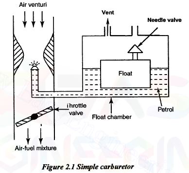 simple carburetor diagram
Working:
During the suction stroke, vacuum is created inside the cylinder. It causes the pressure difference between the cylinder and the outside of the carburetor. Due to this, atmospheric air enters the carburetor. Air flows through the venturi. The venturi increases air speed and reduces pressure. It produces partial vacuum at the tip of the nozzle. Because of this vacuum, the fuel comes out of the nozzle in the form of a fine spray. These fine fuel particles mix with the incoming air to form the air-fuel mixture. Thus, it provides a homogeneous air-fuel mixture to the engine.