What is unfurling and widening of welded pipe joints?
The implementation and arrangement of welded pipe joints is an important link in the manufacture and installation of piping systems. Correct bearing and layout allows pipe joints to be kept in the correct size and shape, making welding jobs easier and more efficient. Below is a brief introduction to the basic process of deploying and arranging pipe fittings:
- Selection of appropriate settlement method : According to the shape, size and application scenario of the pipeline, the appropriate deployment method is selected. Commonly used methods include: direct measurement, geometric methods, mathematical methods, and use of computer software.
- Calculate the size of the split :
- For traditional straight pipes, the developed length corresponds to the actual length.
- For elbows or conic sections, you may need to use trigonometry or other mathematical formulas to calculate the unfolded dimension.
- Create a release template : A release template can be made from cardboard, plastic sheets, or thin sheets of metal. This can be used as a reference when cutting and shaping hardware.
- Release : Using the template or based on previous calculations, mark the lines to be cut and formed in the raw material.
- Cutting and shaping : Cutting and shaping are done according to approved lines using appropriate tools (e.g. cutter, tube bender, etc.).
- Test Assembly and Fit : Before soldering, do a test fit to ensure that the dimensions of each part are correct and the interface fits. Small adjustments can be made if necessary.
- Welding: Welding is carried out in accordance with welding requirements to ensure weld quality.
1. The basic principles and methods of unfolding and modeling
1.1 Extension of the three sampling principles
- Precise and accurate principle: The implantation method must be correct, the implantation calculation must be accurate, the actual length must be accurate, the implantation drawing must be accurate, and the sample plate must be accurate. Since there may be errors in cutting and unloading in the future, the accuracy of the releasing process needs to be higher and the overall error is ≤ 0.25mm.
- Technically viable principle: The sampler must be familiar with the process and the process must be approved. This means that the sample can be collected but also deciphered, and this must be easy to do and not cause problems during subsequent production. The center line, bending line, reserved assembly line and other elements required for future processes must be marked on the sample plate.
- Economic and practical principle: For a given production unit, what is theoretically correct is not necessarily operational, and what is advanced is not necessarily viable. The final program should be based on existing technical requirements, process factors, equipment conditions, outsourcing opportunities, production costs, working hours, personnel quality, financial constraints, etc. Taking into account the situation, specific problems and specific analyses, we strive to find economically viable, simple and quick, practical and economical solutions. We will find an economically viable, simple, fast, practical and economical program that cannot be surreal and that is not disconnected from the productive capacity of the existing technological system.
1.2 Three methods of unfolding and sharing
To draw the development drawing on the same plane, we need to know the actual length of the lines that form the replacement surface. There are two ways to find these real lengths, that is, find the real lengths, either by calculation or by geometric drawing. Various other claimed settlement methods like table method, proportional method, etc. are derived from this. These two possibilities result in two methods, and with computer-assisted unwinding and assisted cutting very promising, the unwinding methods can be summarized into three:
- 1) Geometric deconvolution method
- 2) Computer-aided deconvolution method
- 3) Computer-aided unfolding
Geometric unfolding
The geometric deconvolution method should more accurately be called the geometric graphical deconvolution method. In the unfolding process, the actual length and unfolding diagram design are created by geometric drawings. The geometric method can be divided into several practical methods. Three are commonly used: a. radial line method; B. parallel line method; w. Triangle method.
Calculation method
Computer-aided unfolding, as the name suggests, involves calculations. In fact, unfolding only uses the calculation method to find the actual length. When drawing the unfolding diagram, a geometric design is still used.
Computer-aided unfolding
One of the applications of computers in sheet metal design and manufacturing is computer-aided unfolding and cutting, and both can even be performed simultaneously on CNC cutting machines. There are several computer-aided unfolding application software, mainly focused on designing thin sheet metal parts with unfolding capabilities. The method is divided into two categories, namely parametric modeling and feature modeling.
1.3 Three sample plates for commonly used sampling
Application and classification of sample plates
To avoid damage to the steel sheet, we usually do not place the samples directly on the steel sheet, but make the samples by placing the samples and drawing lines on the steel sheet according to the samples.
When releasing samples, three samples should generally be taken:
- The. Unfolding samples for unloading;
- B. Forming samples to determine the degree of bending during forming;
- w. Mounting sample to determine the relative angular position of the mounting sample. The last two samples are commonly called map samples.
1.4 Sample Materials and Manufacturing
Metal materials commonly used to make samples are thick cardboard, linoleum and thin iron. These metallic materials have strength depending on your needs: cardboard is cheap and suitable for small samples; Felt piecing is practical, suitable for drawing a large unfolding of the map, widely used, but cannot be used frequently; Although the thin sheet is expensive for sample production, it has good strength and rigidity, accurate and durable, easy to store, mainly for mass production, but also as a preferred board prototype for the material.
2. Reducer unfolds sample release
2.1 Reducer surface properties
The upper and lower openings of the reducer are parallel, it is a round tube diameter when using connectors, there are concentric and eccentric points. The surface of the concentric reducer is a positive conical surface and the surface of the eccentric reducer is an oblique conical surface; they are all straight surfaces.
A so-called straight surface is a bus that moves outward from the surface according to a certain rule along a baseline in space. The bus has a position line at each point on the baseline, which is called the main line at that point. Obviously surfaces are composed of polylines.
Concentric reducers are often used for riser reductions for horizontal reducers, 90° eccentric reducers are used for high requirements.
2.2 Unfolding the concentric reducer
1) Known conditions
- The central diameter of the big head: ΦD = 120;
- The central diameter of the small head: ΦX = 60;
- Height: h = 100;
-
The planes of the large and small heads are parallel to each other, and the projection of the center of the small head onto the plane of the large head coincides with the center of the large head.
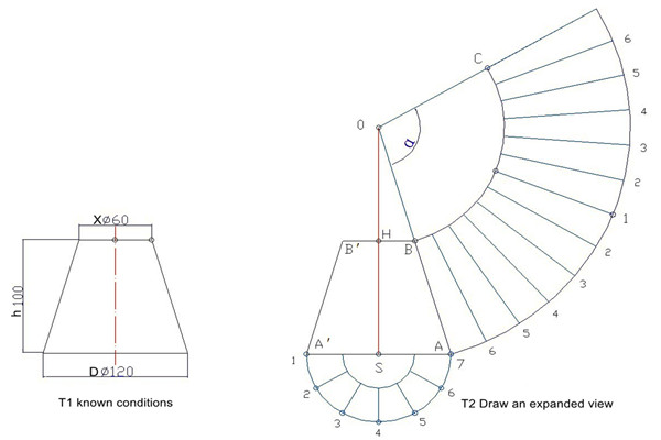
Figure 1: Example of expansion of a concentric reducer
2) Steps to unfold:
(1) Take the horizontal plane as the base of the big head and create the elevation under the known conditions, that is, define HS ⊥ SA, where HS = h, SA = ΦD/2; set HB//SA over H, HB = ΦX/2;
(2) Extend the hypotenuse AB of the conical table until it intersects the central axis extension line HS at point O. Take O as the center of the circle and draw arcs with radii OA and OB.
(3) Measure arc AD to arc OA so that the length of the arc is equal to the circumference of the base circle (L = πΦD).
(4) Connect OD and cut the arc OB with C; then sector ABCD is the desired extended value.
(5) Note: It is not advisable to measure the circumference of the small head circle on the OB sheet first. Since the OB measurement error is outside the arc (OA arc) in the error amplification, this may result in the allowable tolerance range being exceeded.
(6) The outer diameter can also be determined by calculating the angle of the center of the unrolled sector circle. The angle of the center of the circle can be calculated using the following formula: 
Substituting the known conditions of this question, we obtain α = 103.4°
(7) Figure 2.a, on line AA′ below the top half of the puzzle, the bottom circle consists of 6 equal pieces and intersects the same points to draw vectors. When unfolding the figure, also make pieces of the same size and cross the same points to draw vectors.
2.3 The extension of the eccentric reducer
1) Known conditions
The central diameter of the large head Φx, the central diameter of the small head Φs, the height of the inclined conical table h, the eccentricity distance e, the parallelism between the top and bottom of the inclined conical table, and the symmetry with respect to the central plane 0S7.
2) Expand and analyze
(1) In △0S6, 0S is the height of the inclined cone, 06 (thick line) is the main line, and S6 (dashed line) is the projection in the top view. Since 0S is perpendicular to the base, △0S6 is a right triangle; ∠0S6 is a right angle; and the main line 06 is the hypotenuse of this right triangle. This is the basis for determining the actual length of the hypotenuse from the hypotenuse cone. 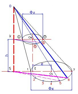
Figure 2-a Known conditions and analysis of the real length of an oblique cone
(2) The conical table is actually formed by cutting the upper small cone from the same inclined cone. Obviously, a similar relationship also exists in the composition of the unfolded diagram. When unfolding, we first deal with the large cone and then release the small cone.
3) Draw the elevation and top view based on known conditions.
Attention: When drawing a view, use the central diameter as the default. If the specified condition is the outer diameter or pitch circle diameter, the pitch circle diameter must first be determined based on the thickness of the plate.
4) Calculate the actual longitude using ∠ OS7 as 90°.
5) Draw an expansion diagram
- (1) Take 01 as the cutting line and draw the center line 07 vertically at a suitable location.
- (2) Draw arcs 1, 2, 3, 4, 5 and 6 as shown in Figure 2.b, where point S is the center of the circle and the actual length of the isolines at each point is the radius.
- (3) Draw an arc with 7 points as the center and 1/12 of the base perimeter as the radius, cut 6 arcs at two points of 6, then draw an arc with two points of 6 as the center and 1/12 of the base perimeter like the radius, cut 5 arcs into two 5 points; Continue like this and find two points 1 using the same method;
- (4) Check the length of the curve of the 13 points obtained. If the error in the calculated base circumference is greater than 3 mm, it should be corrected in time.
- (5) Smooth connection of large opening expansion tubes at different points;
- (6) Connect point 0 to each point as shown in the figure, and measure the corresponding actual length of the small cone of point 0 on each of the lines above. The points obtained by soft connection form a small opening expansion line.
- (7) Connect the corresponding endpoints of the large and small openings to complete the entire expansion diagram.
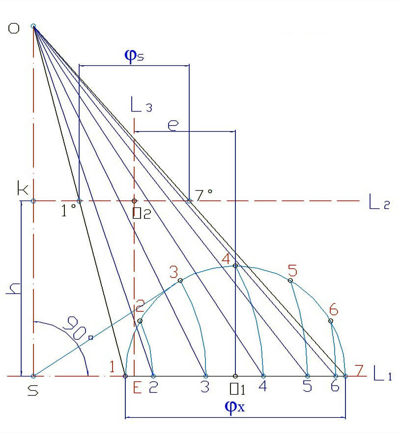
Figure 2-b Extension of the diagonal cone – determination of the real length
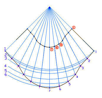
Figure.2-c Oblique cone expansion diagram
3. Unfolding the elbows
3.1 Round tube welding elbow and its main parameters
Elbows are connectors used to turn pipelines. According to the caliber classification, contra-angles can be divided into equal-sized contra-angles and reducing contra-angles. According to the classification of production methods, elbows can be divided into elbows, pressing elbows, extrusion elbows and welding elbows. According to the cross-sectional shape, they can be divided into round tube elbows, square tube elbows, square tube conversion elbows, reducing elbows and irregular conversion elbows.
The arc extension mentioned here is a “shrimp arc” formed by assembling and welding segments. These mainly include equal diameter round elbows, decreasing diameter round elbows, and square and round pipe conversion elbows.
Welded arc and its main parameters
- Some main parameters for elbow welding: (see Figure 3.a)
- Arc angle: refers to the angle between the two nozzle surfaces of an arc;
- Elbow diameter: Refers to the outer diameter, inner diameter or partial diameter of the elbow pipe material;
- Radius of curvature: Refers to the radius of the inner circle of the axis of the pipe segment. The distance from the center of the nozzle to the intersection of the two nozzle surfaces;
- Number of Arc Sections: The end section of the arc is half of the middle section and the two end sections together form one section. The sum of the number of intermediate sections results in the number of arc sections.
3.2 Unfolding angled pieces of equal size
1) Known conditions and requirements for elbow use
(1) Known medical conditions
- Flexion angle: α = 90°;
- Tube outer diameter: Φ B = 60;
- Bending radius: r = 150
- Number of angular pieces: n = 3;
- Stencil thickness: δ = 0.5
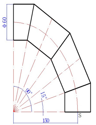
Figure.3.a Known elbow conditions
2) Deployment requirements
- ① The parallel line method is used to produce the outsourced full section model for pipes with an outer diameter of Φ60.
- ② The method is correct.
- ③ Accurate drawing: Geometric drawing error ≤ 0.25, unfolding length error ≤ ± 1.
3) Preparation for deployment
① Calculate the half section angle: Calculate the inclination angle of the half section (end) based on the number of sections( α b = α/2n ).
② Layout processing: Determine the diameter of the stakeout pitch circle, interface position and margin based on the pipe diameter, material plate thickness, connection method and manufacturing process.
4) Search for Truth and Strength:
(1) According to the known conditions, first draw the angular line ∠ BOK of the elbow half section, and then draw the plan view of the elbow half section 1′ 177′, where OS=R;
(2) Use the pipe mouth line in the view as the center line of the top view and assemble half of the top view.
(3) As shown in the figure, when the nozzle circle is divided into 12 equal parts in plan view, the length of the line segment compressed between the two sides of the half division angle is the actual length of the main line passing through each point of the same size and OB is aligned perpendicular to each partial point of equal size. 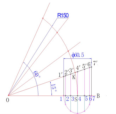
Figure 3.b: Diagram of the actual arc length
5) Draw an unfolded diagram of an elbow
Steps to develop a chart:
(1) Calculate the unfolded length: L = p (60 + 0.5) = 190;
(2) Form a family of parallel primary lines: take AB = 190 on the extension line OS, divide AB equally by 12, and draw perpendicular lines AB through each point of equal division.
(3) Find the expansion curve of the door: pass parallel AB lines through the end points of each solid line to find each expansion point, and connect each expansion point smoothly.
(4) Draw a complete diagram of the section length. 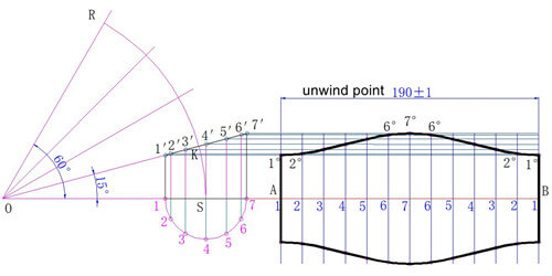
Figure 3.c Elbow deployment diagram
6) Straight pipe cutting
When making elbows, the sample is usually wrapped directly onto the tube to be cut. Larger diameter rolled sheets can also be rolled into tubes before being slit and cut into sheets. In this way, direct cutting has become an important operation.
(1) First calculate the length of the straight pipe.
(2) When cutting, on the quarter circumference of the pipe end, four contour lines should be drawn along the axial direction as a reference line for the alignment of the retrieval jig, and the positioning points should be marked according to o pre-calculated data.
(3) Using a template, draw lines according to the reference line, analyze any errors, and adjust and correct them in time.
(4) Each reference line is also an important alignment point in elbow assembly. To prevent the drawn lines from being erased during work, it is best to drill some points or make other marks on the reference line. 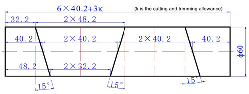
Figure 3.d: Straight tube cutting diagram
4. Expansion of starting points
4.1 T-piece and its main parameters
A tee is an accessory used when a pipe leaves a branch. A tee with the same diameter as the main pipe is called an equal-diameter tee, while a tee with a different diameter is called a reduced-diameter tee. The intersection of the center line of the branch pipe and the center line of the main pipe at an angle of 90° is called a straight tee, otherwise it is called a diagonal tee. If the center line does not cross, it is called a partial tee. A T-piece with different cross-sectional shapes between the branch and main pipes is also called a special-shaped T-piece. The focus of this training can only be on making round tube tees, which is not very difficult.
The main parameters of a circular tee include: the angle of the tee; the diameter of the main and branch pipes; the eccentricity of the branch pipe relative to the main pipe; other relevant sizes. The development of a circular tee is done using the parallel lines method, as is the development of a circular pipe elbow.
4.2 Unfolding the side T-pieces
1) The known conditions are shown in Figure 4.a:
- Main tube outer diameter: Ф88.5
- Branch pipe outer diameter: Ф88.5
- Centerline angle: 45°
- Sample thickness: 0.5
- The shortest distance from the end of the main and secondary lines to the opening is 50.
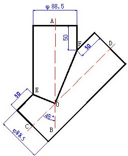
Figure.4.a Known conditions for 45° Equal side T-pieces
2) Need for expansion
- (1) Prepare a sample from the outer casing of the branch pipe and a sample from the opening of the main pipe;
- (2) The method is correct and the drawing is accurate.
3) Expand and analyze
- (1) The two tubes with the same diameter are contiguous and their center lines intersect. Since the diameters are equal, the solid line cannot be moved to one side. Therefore, the connected line in the height diagram can only be the bisector of the center line.
- (2) If you look at the branches ∠A0C and ∠A0D in the diagram, you can see that they are actually two different angles within half of the arc. Therefore, the branch expansion is the same in the arc expansion method.
- (3) The deconvolution curve must consist of two half-wave sinusoids connected by a phase difference of 180°.
4). Deployment process
(1). Find the actual length (see Fig. 4.b)
- ① Draw the height of the branch pipe according to the center diameter of the outer packaging sample roll.
- ② Matching design with half section of garden pipe and 6 equal parts of semicircle;
- ③ The actual length of the branch pipe at each point is equal to the center line.
(two). Branch pipe expansion drawing
(1) Create a series of parallel lines according to the length (89π) and the number of equal parts (12).
- ① Take the extension points on the corresponding parallel lines corresponding to the corresponding actual lengths;
- ② Connect the dots smoothly and complete the unfolding diagram.
(3). Draw the opening of the main tube. (Figure 4.d) 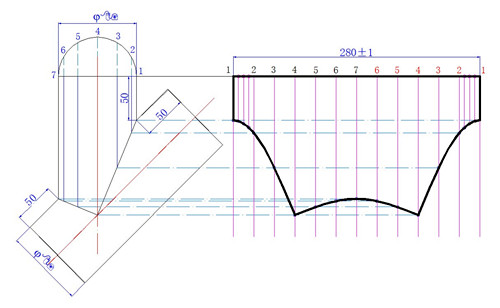
Figure 4.b Expanded diagram of a lateral T branch
4.3 Reducing connector extension
1) Known terms and conditions
(1) Known diseases:
- Branch pipe outer diameter: Φ70;
- The outer diameter of the main tube: Φ80;
- Axis intersection and angle: 45°;
- The distance from the intersection point on the middle surface to the end of the tube is 50;
- To ensure the symmetry of the central surface, the two axes are on the surface.
(2) The production of an oblique T by inserting the outer shell of the sample plate and the main tube of the sample plate with open holes;
(3) Analysis: The key to this problem is to draw the line of coherence of the two pipes on the elevation drawing. To draw a coherent line, first find the key points on the line and then connect the points into a line. To acquire the coherent points, we use the trajectory method learned previously to solve the problem, that is, drawing the surface of the main tube and the surface of the branch tube from the central surface 17 at an equal distance from the trajectory point and the intersection of the approach. The expansion of the branch and the expansion of the main opening with the same T extension with the same diameter.
2) Find the intersection: 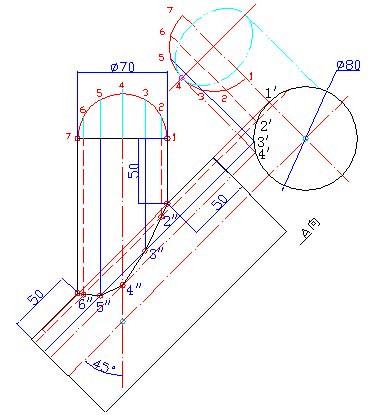
Figure 4.c Reducing tee cutting line
3) Unfolding the insertion tube:
4) Open hole implantation: 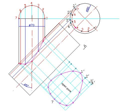
Fig. 4.d Development of openings for a main pipe of a reducing branch
5. Conclusion
This is just the basic process of implementing and arranging welded pipe joints. The specific steps and methods may vary depending on the actual project requirements and specifications.


