Carburization:
The process of preparing a fuel-air mixture outside the engine cylinder in the SI engine is known as carburization.
Important factors affecting the carburization process are given below;
- time available for preparation of the mixture, i.e. atomization, mixing and vaporization
- Inlet air temperature
- quality of fuel supply
- combustion chamber and induction system design
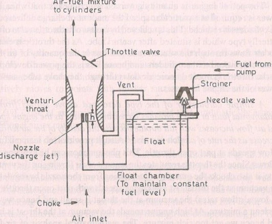 Simple Carburetor
Simple Carburetor:
Complete carburetor:
Additional systems used with simple carburetor can help the engine to operate in all conditions, which are given below,
(i) Main measurement system:
The different measurement systems are,
Compensating jet device: – In addition to the main jet, a compensating jet is provided to provide the thinning effect.
Emulsion tube or air bleed device:
- Mixture correction is done only by air bleeding
- In this arrangement, the main metering jet is installed about 25 mm below the gasoline level, called a submerged jet .
Reverse suction or pressure reduction control method:
- In this arrangement, a large vent line connects the carburetor inlet with the top of the float chamber and another small orifice line is connected with the top of the float chambers with the vent throat.
- Creates pressure differences depending on engine operating conditions
Auxiliary valve carburetor:
- The auxiliary valve spring lifts the valve during increased engine load, which increases vacuum when venting
- Allows more additional air intake and the mixture is not too rich
Auxiliary Port Carburetor:
- The butterfly opening allows greater air inductance, which reduces the amount of fuel sucked in
- Used in aircraft carburetors
(ii) Idle system:
- Idle jet is added for idling and low load operation, which requires a rich mixture with A/F ratio of about 12:1
- It consists of a small fuel line that runs from the float chamber to a point on the throttle side
- Gradually opening the throttle may stop the jet from idling
(iii) Enrichment or energy saving system:
- This system provides a richer mixture for a maximum operating power range
- Features large orifice metering rod economizer that opens to the main jet as the throttle is opened beyond a certain point
- The stem is tapered or stepped
(iv) Acceleration pump system:
- Engine acceleration condition or rapid increase in engine speed may open the throttle quickly, which will not be able to provide a rich mixture
- Spring-loaded plunger acceleration pump is used for fuel supply
(v) Suffocation:
- A rich mixture is required during the cold starting period, at low starting speed and before the engine is warmed up.
- Butterfly or choke valve is used between carburetor inlet and engine throat to meet the requirements
- Spring-loaded bypass choke is used at higher speeds
Reference
: IC Engine Textbook by Mathur Sharma