CNC laser cutting machine is a machine tool that uses laser as a cutting tool to process workpieces. The main hardware includes machine base, cross beam, work table, laser, cutting head, stabilizer, cooler, electrical control cabinet, gas source (oxygen, nitrogen, air), etc.
The system includes electrical system, mechanical system, air passage system, optical system, hydraulic system, lubrication system, cooling system, etc.
In this paper, static and modal finite element analyzes were conducted on the important component of the CNC laser cutting machine – the Y-axis beam. The three-dimensional finite element method was used to analyze the deformation of the Y-axis beam under various typical conditions work, extract the deformation law, establish a three-dimensional model based on SolidWorks software, and conduct finite element analysis of the beam using Simulation. module.
Based on this, a modal analysis was performed on the Y-axis beam to resolve the natural frequencies of the first five orders and the corresponding vibration modes, to verify the feasibility of the design structure, and to provide a theoretical basis for the size of the structure. and mechanical equipment optimization design.
CNC laser cutting machine is an ideal equipment for sheet metal processing, widely used in industries such as switch cabinets, computers, textile machinery, instruments and meters, automobiles, elevators and grain machinery, both domestically and internationally.
Laser belongs to dieless processing, with strong processing flexibility, which can shorten the development cycle of new products in the sheet metal industry, improve product accuracy and interchangeability, and is particularly suitable for small batch processing of various varieties .
The deformation and vibration of the Y-axis beam in actual work will directly affect the processing accuracy of the laser cutting head.
To ensure the practicality and processing accuracy of the equipment, the real structure is discretized into element grids using the finite element method. Each element has a simple shape and is connected through nodes. The unknown quantity in each element is the displacement of the node. The stiffness matrix of each individual element is combined to form the overall stiffness matrix of the entire model. The stress of each element is calculated by the change in displacement at the node.
Working principle and beam structure of CNC laser cutting machine
The laser cutting industry has undergone more than 60 years of development since its inception in 1960. It has undergone several major changes, from YAG (crystal laser) to CO2 (carbon dioxide laser) and now to fiber laser .
The working principle of a laser cutting machine is that the laser beam generated by the laser is emitted through the lens to focus on a small spot at the focal point. The spot heats the material and the laser beam moves along the material to complete the cutting process.
CNC laser cutting machines use a gantry structure. The sliding saddle moves along the X-directional guide rail on the bed, while the cross beam is equipped with a horizontal (Y-directional) linear guide rail. The Z axis component is connected to the Y directional guide rail through a slider, and the laser cutting head is installed on the Z axis slide plate. The bed is fixed on the foundation and can be viewed as a rigid body.
Due to the large length-to-diameter ratio and flexibility of the Y-axis cross beam, it is prone to deformation and therefore becomes one of the main components that affect the accuracy of laser cutting machines.
The Y-axis structure is shown in Figure 1, where the transverse beam has a support function, requiring the material to have good rigidity and toughness, as shown in Table 1.
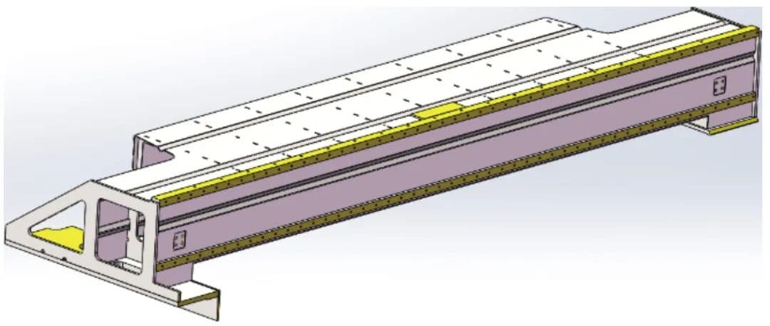
| Material type | Q235-A Welding |
| Density | 7,860 kg/ m3 |
| elastic modulus | 212GPa |
| Poisson's ratio | 0.288 |
Establishing a Finite Element Calculation Model for the Y-Axis Cross Beam
Before analyzing the model, the Y-axis cross beam is simplified based on the characteristics of the main structure and the workload of the laser cutting machine. After simplification, a simplified solid finite element analysis model of the Y-axis cross beam is established, as shown in Figure 2.
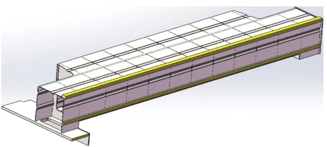
(1) The overall structure of the CNC laser cutting machine is symmetrical and the supporting forces are basically balanced. The Y-axis cross beam is made of 2.5mm thick steel plate bent with a 20mm thick guide rail mounting plate and undergoes vibration annealing and aging treatment. The structure is relatively symmetric in the Y/Z plane, and the external force is mainly in the Y/Z plane, and the deformation mainly occurs in the Y/Z plane.
(2) The dimensions of the chamfers and threaded holes relative to the Y-axis cross beam are small and can be ignored. Components such as the damping plate and connecting transition plate help to increase the stiffness of the cross beam. Ignoring them will not affect the actual engineering requirements.
(3) When the cutting machine is in operation, the Y-axis cross beam mainly bears the effects of concentrated force and inertia force.
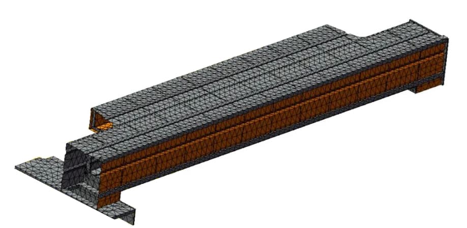
The solid model is created using SolidWorks and then simplified before being imported into Simulation for meshing. Based on the complex nature of the actual structure, the mesh is manually adjusted after automatic meshing. Figure 3 shows the actual mesh structure after mesh generation, with a total of 35,388 elements and 55,241 nodes.
| Example name | Application analysis |
| Mesher used | default grid |
| Automatic transition | to close |
| Includes automatic mesh ring | to close |
| Jacobi Point | four points |
| Jacobi ladle inspection | Open |
| Cell size | 41.9985mm |
| Tolerance | 2.09992mm |
| Grid quality | high |
| Total number of nodes | 55241 |
| Total number of units | 35388 |
| Time to complete the grid (hour: minute: second) | 00:00:41 |
The Y-axis cross beam is fixed and connected to the transition plate by means of M10 bolts, which move together with the sliding saddle in the X-axis direction. According to the mechanical properties of the load and its distribution in the structure, the load can be divided into the following categories:
(1) Concentrated load. This load is caused by the weight of the Z-axis component on the cross beam, and its application point varies with the position of the Z-axis component on the cross beam. Therefore, the weight of the Z-axis component can be treated as a concentrated load and various transverse positions can be analyzed. The concentrated load acting on the Y axis transverse beam is F_concentrated = m_Zg = 80 × 10 = 800N.
(2) Distributed load. This load is mainly due to the weight of the Y axis. The center of mass of the cross member is always at 0.5L, so the weight can be carried as a distributed load. The distributed load acting on the Y-axis cross beam is F_distributed = m_Yg = 181.91 × 10 = 1819.1N.
(3) Inertia load. The movements of the CNC laser cutting machine in three directions are controlled by the motor. When the engine is turned on, the Y-axis cross beam will produce acceleration in the Z)ax = (181.91+80) × 15 = 3928.65N.
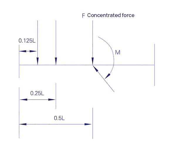
Based on the above conditions, a mechanical model of the Y-axis cross beam is established, as shown in Figure 4. The concentrated load is applied to the central position when loaded. The inertial force of the X-axis acceleration on the Y-axis is carried as a surface charge. According to the principle of force translation, the weight of the Z-axis component is simplified as a force and moment acting at the center of the cross beam.
Deformation Analysis of Y-Axis Cross Beam
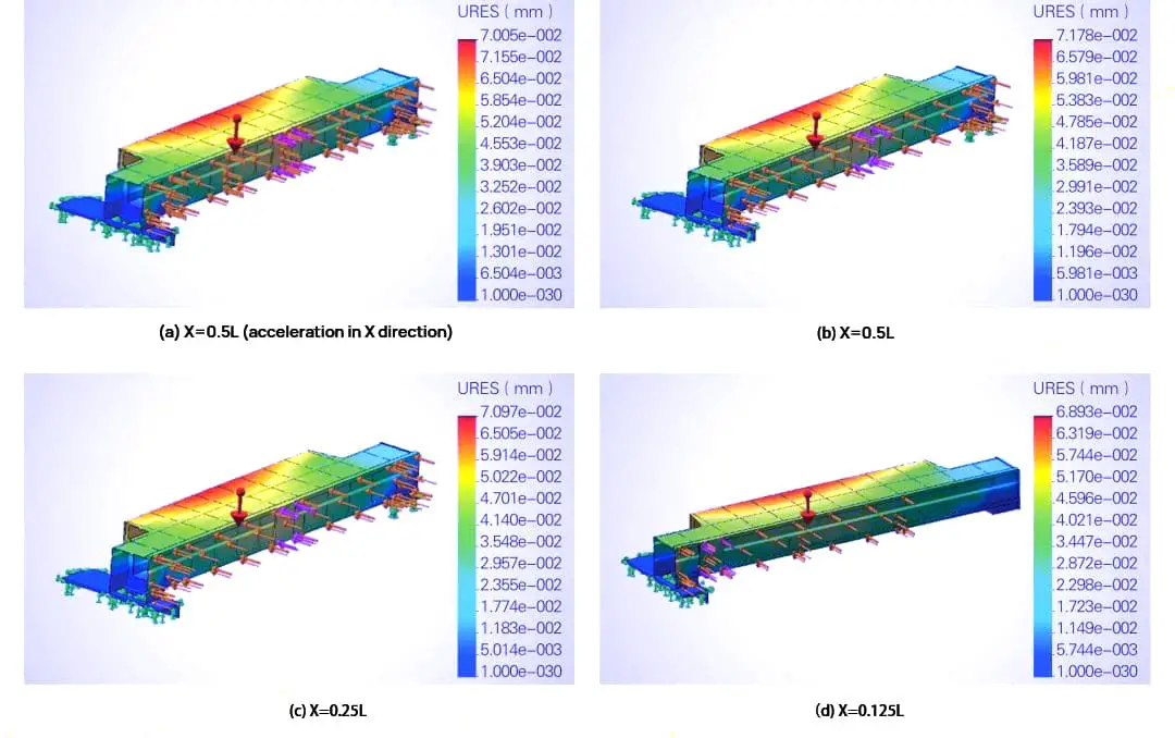
Finite element analysis of the Y-axis cross beam was performed using Simulation to obtain the strain distribution within the operating range of the laser cutting machine, which was used to check the forming quality under the following two working conditions:
- Load distribution settings. Finite element analysis was performed at three positions within the total length L: 0.5L, 0.25L and 0.125L.
- Acceleration impact analysis. The lateral deformation (in the Z direction) caused by the inertia force along the Y axis during starting is negligible. The inertia force along the Z axis was treated as a concentrated load. Therefore, the main focus is on the effect of the inertia force caused by the startup acceleration along the X axis on the deformation of the Y axis cross member, to obtain the deformation of the Y axis cross member under the worst working conditions.
The calculation results are presented in table and contour map format, as shown in Table 2 and Figure 5.
Table 2: Maximum deformation values (mm) of the beam with concentrated load in different positions.
| Position | 0.125L | 0.25L | 0.5L |
| Maximum deformation | 6.893e-002 | 7.097e-002 | 7.178e-002 |
Modal Finite Element Analysis of Y-Axis Cross Beam
Modal analysis refers to the process of solving eigenvalues and eigenvectors, also known as mode extraction. The inherent frequency and vibration mode of the girder were obtained using simulation frequency analysis. The frequency number was set to 5, which represents the 5th order mode. The direct sparse solver (sparse matrix solver) was selected to accelerate the solving speed. The parameters of the first five modes are shown in Table 3. The vibration mode deformation diagram of the cross beam for each mode with different frequencies is shown in Figure 6.
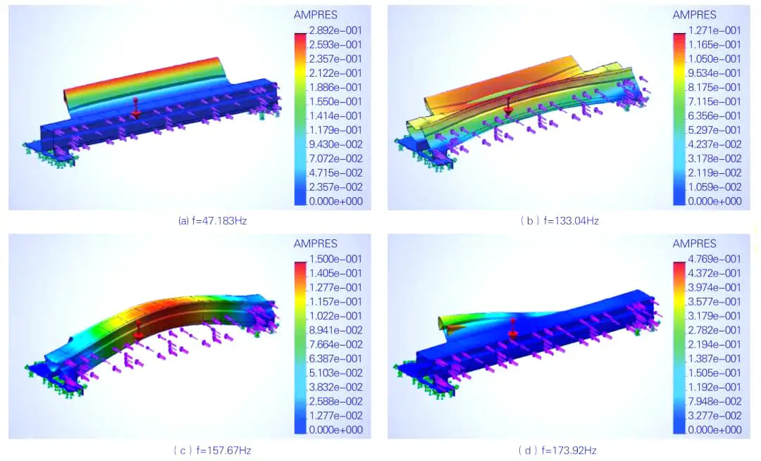
Table 3 Modal solution results
| Modal order | 1 | two | 3 | 4 | 5 |
| Natural frequency /Hz |
47,183 | 133.04 | 157.67 | 173.92 | 211.85 |
Conclusion
The deformation of the Y-axis cross beam is related to the position of the Z-axis components. The closer the Z-axis components are to the center of the cross beam, the greater the deformation. The maximum deformation occurs at the center position and is less than 0.3 mm, which meets the engineering requirements of controlling deformation within 2 mm.