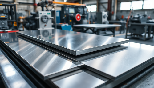
Laser cutting technology has gradually replaced traditional metal processing methods due to its low processing cost, fast production efficiency, precise cutting accuracy and excellent processing quality. This technology is widely used in the processing of carbon steel, stainless steel, copper, aluminum and other non-ferrous metals and is considered irreplaceable in these areas.
However, with the widespread use of laser cutting technology, some problems have arisen. One of the most significant problems is that when cutting carbon steel sheets with the same thickness and different compositions using the same laser cutting machine and cutting process parameters, there are noticeable differences in the surface quality of the cuts.
To understand the impact of sheet composition on cutting quality, tests were carried out on carbon steel sheets with different thicknesses and compositions, using fiber lasers with power ranges from 6 to 30 kW and cutting with oxygen and air.
Related reading: The application of air as an auxiliary gas in laser cutting
1. Experimental equipment and methods
1.1 Experimental equipment
The experiment was conducted using a 30KW fiber laser, which is a continuous output multimode laser with a beam wavelength of 1080 nm and a core diameter of 150 μm. The laser head used in the experiment was the Genius 30 laser head (30KW).
The near-diameter focal length of the laser head was 100 mm, and the focusing mirror had a focal length of 200 mm, which allowed automatic focusing. To ensure the stable operation of the 30KW fiber laser and maintain its optimal performance, a water chiller with a cooling capacity of 70.0KW was used as auxiliary equipment.
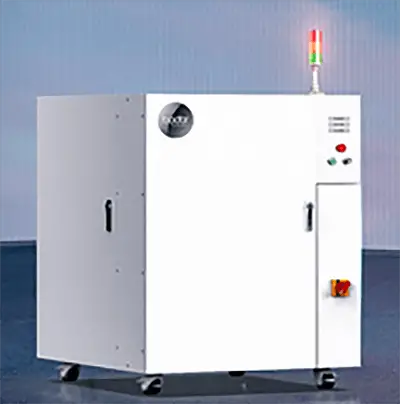
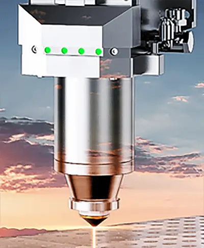
Figure 1 – Experimental laser, laser head
1.2 Auxiliary materials
To ensure the accuracy, efficiency and clarity of experimental data, the test materials used in this experiment were carbon steel plates of different thicknesses, including Q235, Q345 and Q460 carbon steel. For details, see the experimental board datasheet.
The auxiliary gas used was 99.9% oxygen, with an air supply pressure of 5bar. To ensure a sufficient number of nozzles, the nozzles listed in the experimental nozzle data sheet were prepared for the experiment.
Table 1 Experimental Plate Data Sheet
| Material Type | Q235 | Q345 | Q460 | Q690 | NM400 | 45# | T10 |
| Size/mm (L/W: 500/500) | 12 | 12 | 12 | 12 | 12 | 12 | 20 |
| 16 | 20 | 20 | 20 | 16 | 16 | 30 | |
| 20 | 30 | 30 | 30 | 20 | 20 | 40 | |
| 30 | / | / | / | 30 | 30 | / |
Table 2 Experimental Nozzle Data Sheet
| Nozzle type | Double jet | Single jet | ||||
| Nozzle model | B-1 | B-2 | B-3 | D-4 | D-7 | D-9 |
| Amount | 5 | 5 | 5 | 5 | 5 | 5 |
1.3 Experimental methods
Under the condition that the spot quality of the equipment (optical fiber and laser head were clean and undamaged, verified through a photo paper test), air pressure (oxygen was kept stable at 5 bar and the air was kept stable at 11 bar), and the internal lenses of the laser head (clean, free from dirt and burn marks) were normal, the internal modules were controlled via the laser's internal control software and the maximum output power was adjusted to 12KW, 20KW and 30KW respectively.
Cutting experiments were carried out on different types and thicknesses of plates described in Table 1, under the three power states mentioned above. The perimeter of the cut sample was 205.6mm, as shown in Figure 2.
The cut samples were analyzed and compared by examining the porosity density, roughness, and corresponding process parameters on the surface of the cut samples.
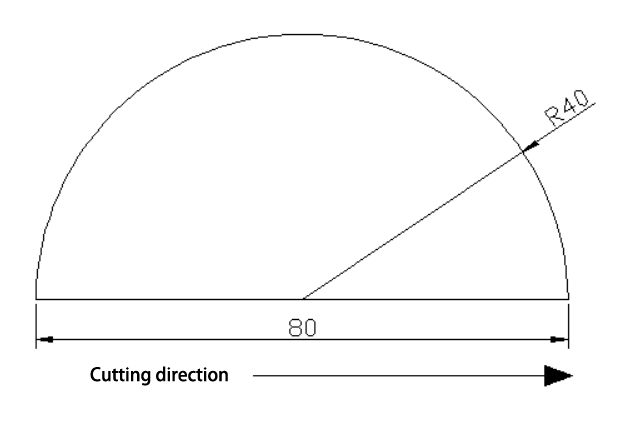
Fig. 2 – Schematic Diagram of the Cutting Sample
2. Test results
2.1 Analysis of cutting parameters
During the experiment, the five factors affecting the cutting speed (laser power, cutting gas pressure, focus and nozzle opening) were taken into consideration to ensure that the samples after cutting would detach automatically, without slag, burning , droplets and have a high surface finish. Process parameters have been adjusted to obtain the best cutting effect for different materials and thicknesses.
Related Reading: Laser Cutting Thickness and Speed Chart
See Table 3 for specific parameters.
Table 3 Experimental Parameters Table
| Plate | Thickness/mm | Power | Speed m/min | Air pressure/bar | Power/KW | Focus/mm |
| Q345B | 12 | 12KW | 1.7 | 0.8 | 9600 | 9.8 |
| 20 | 1.4 | 0.6 | 12,000 | 11.6 | ||
| 30 | 0.9 | 0.7 | 12,000 | 12.5 | ||
| 45# | 12 | 1.9 | 1.2 | 10,000 | 9.8 | |
| 20 | 1.6 | 1.5 | 12,000 | 9.5 | ||
| 30 | 1 | 0.6 | 12,000 | 12.3 | ||
| NM400 | 12 | 1.6 | 1 | 9,000 | 9.6 | |
| 20 | 1.5 | 0.45 | 12,000 | 12 | ||
| 30 | 1 | 1 | 12,000 | 12 | ||
| Q345B | 12 | 20KW | 1.7 | 0.8 | 9600 | 9.8 |
| 20 | 1.6 | 1.3 | 16,000 | 12 | ||
| 30 | 1.2 | 1 | 17,000 | 12.5 | ||
| 45# | 12 | 1.9 | 1.2 | 10,000 | 9.8 | |
| 20 | 1.6 | 1.3 | 14,000 | 12 | ||
| 30 | 1.2 | 1.5 | 16,000 | 11.5 | ||
| T10 | 20 | 1 | 1.4 | 15,000 | 11 | |
| 30 | 0.8 | 1.6 | 18,000 | 11.5 | ||
| 40 | 0.7 | 1.7 | 18,000 | 11 | ||
| NM400 | 12 | 1.6 | 1 | 9,000 | 9.6 | |
| 16 | 1.8 | 0.55 | 14,000 | 12 | ||
| 20 | 1.5 | 0.6 | 14,000 | 12.5 | ||
| 30 | 1.1 | 0.85 | 17,000 | 12.5 | ||
| Q345B | 35 | 30KW | 1.3 | 1.8 | 30,000 | 12 |
| 40 | 0.85 | 1.2 | 24,000 | 12.5 | ||
| 45# | 30 | 1 | 3 | 26,000 | 13 | |
| 40 | 0.8 | 1.7 | 30,000 | 12.5 | ||
| T10 | 35 | 0.8 | 1.6 | 18,000 | 11.5 | |
| 40 | 0.7 | 1.7 | 18,000 | 11 | ||
| NM400 | 40 | 1.3 | 1.6 | 23,000 | 13 | |
| 30 | 0.8 | 1.7 | 30,000 | 12.5 |
2.1.1 Cutting speed analysis
The data in Table 3 shows that, with a laser power of 20KW as a test background, the cutting speeds of plates with thicknesses of 20mm and 30mm made of Q345, 45#, NM400 and T10 steel were compared, as shown in Figure 3 .
With the same laser power, plate thickness and auxiliary gas oxygen, the T10 plate had the slowest cutting speed, while the NM400 had the fastest. There was no significant difference between the cutting speeds of Q345 and 45# steel.
It can be concluded that the carbon content in the cutting material has the most significant impact on the cutting speed. As the carbon content in the plate increases, the cutting speed of the plate with equal thickness gradually decreases. Furthermore, as the content of rare elements (such as Cr, Ni) in the plate increases, the cutting speed gradually decreases.

Fig. 3-20KW cutting speed comparison
2.1.2 Auxiliary air pressure analysis
Laser cutting of carbon steel with oxygen as an auxiliary gas works by using the energy generated by the laser light source and the oxidation reaction during the cutting process.
It is clear that oxygen pressure has a significant effect on various types of plaques.
Table 4 in the cutting process data of 20mm and 30mm Q345, 45# steel and T10 with 20KW laser, as shown in Table 3, reveals that for different types of sheets with the same thickness, the auxiliary gas pressure increases at As the carbon content in the plates increases, for ideal cutting results.
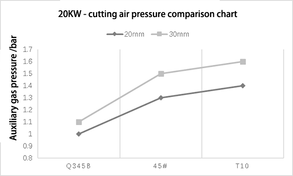
Fig. 4-20KW auxiliary air pressure comparison diagram
2.1.3 Cutting focus analysis
Previous test data shows that when cutting Q235, Q345 steel, 45# steel and T10 steel with the same thickness and using oxygen as cutting auxiliary gas, 45# steel and T10 steel contain more carbon than Q235 and Q345.
During the cutting process, a large number of carbon dioxide pores form on the surface, causing a rough surface.
The cutting effect remains unchanged when the cutting focus changes within ±1, so the focus can be reduced to improve the cutting speed. However, the cropping effect of the Q235 and Q345 is sensitive to the cropping focus, so they do not have this advantage.
2.2 Analysis of the commissioning effect
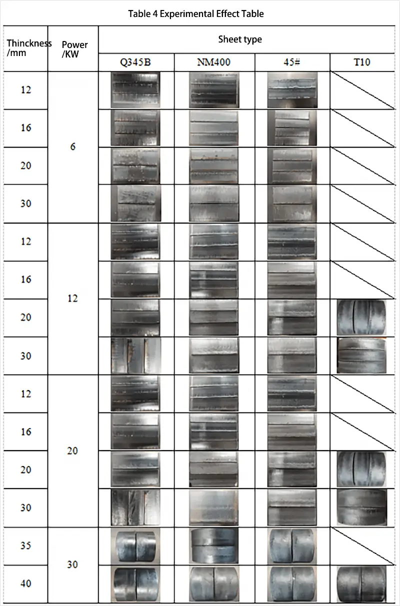
The table below shows the results of cutting different types and thicknesses of sheets using different auxiliary gases and cutting powers.
As shown in Table 4, it is evident that the cutting effects of different types of sheets with the same thickness were compared using the same cutting power.
The results indicated a significant difference in surface roughness between samples cut from different materials, with sample Q345B exhibiting the best cutting effect. The surface oxide film was thin and the surface roughness was minimal.
On the other hand, the oxide film on the cutting surface of sample NM400 showed obvious stratification. The upper side of the cutting surface was smooth, while the lower side had a thicker oxide film, leading to greater surface roughness of the sample.
The cut of the 45# sample was rough, with an obvious protrusion of the oxide film at the bottom.
Sample T10 had the worst cutting effect, with a rough surface, numerous pores and a noticeable oxide layer on the bottom.
In comparison, the Q345B, NM400 and 45# cutting surfaces showed better surface roughness of the oxide layer than the T10 plate.
Table 4 Experimental Effect Table
2.2.1 Analysis of the material’s melting point
This experiment tested four types of materials: Q235, Q345B, NM400 and 45# carbon steel plates. Its carbon content is 0.22%, 0.20%, 0.25% and 0.47%, respectively.
By examining the iron-carbon phase diagram in Figure 5, it can be seen that the melting point temperature of these four materials is approximately 1500°C.
Laser cutting of carbon steel uses the laser as the preheating heat source and oxygen as the auxiliary gas. This creates a highly exothermic oxidation reaction with the materials, releasing a significant amount of oxidation energy (as shown in the following formula).
Fe+O→FeO+heat(257.58kJ/mol)2Fe+1.5O 2 →Fe 2 Ó 3 +heat(826.72kJ/mol)
It was established that the temperature at the plate processing site exceeded 1726.85°C due to the energy released from the laser and the oxidation process during laser processing. This temperature is significantly higher than the melting points of materials Q235, Q345B, NM400 and 45#.
Based on this analysis, it can be concluded that the melting points of these materials have limited impact on the effect of oxide scale on the surface after cutting.
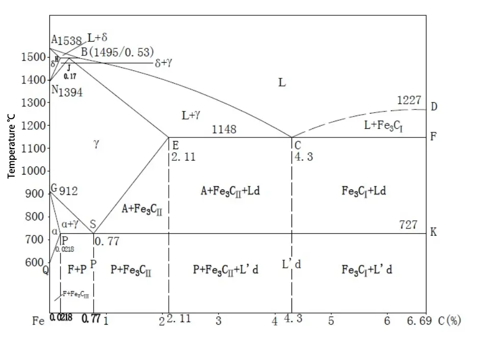
Fig. 5-Fe-C phase diagram
2.2.2 Analysis of the chemical composition of materials
The chemical composition of the different steel plates used in this experiment was determined using a spectrum analyzer. The results are shown in Table 5.
Table 5 Analysis of Chemical Elements
| Chemical element/%/plate type | Q345 | Q235 | Q460 | NM400 | Q690 | 45# | T10 |
| W | 0.2 | 0.22 | 0.2 | 25 | 0.18 | 47 | 1 |
| Mn | 1.7 | 0.65 | 1.8 | 1.6 | two | 0.65 | 0.4 |
| Yes | 0.5 | 30 | 0.6 | 0.7 | 0.6 | 27 | 0.35 |
| s | 0.035 | 0.05 | 0.03 | 0.01 | 0.02 | / | 0.02 |
| P | 0.035 | 0.045 | 0.03 | 0.025 | 0.025 | / | 0.03 |
| Cr | 30 | 0.3 | 0.3 | 14 | 1 | 0.25 | 0.25 |
| No | 0.5 | 0.3 | 0.8 | 1 | 0.8 | 0.3 | 0.2 |
| Ass | / | 0.3 | / | / | 25 | 0.3 | |
| Mo | 0.1 | / | / | 0.5 | 0.3 | / | / |
| No. | 0.07 | / | 0.11 | / | 0.11 | / | / |
| V | 0.15 | / | 0.2 | / | 0.12 | / | / |
| You | 200 | / | 0.2 | / | / | / | / |
| AI | 0.015 | / | / | / | / | / | / |
| B | / | / | / | 0.004 | 0.004 | / | / |
1) Content analysis of the Mn element
According to Table 5, which compares elements Q235 and Q345B, both materials are classified as low carbon steel. The content of other elements in the materials does not differ significantly, except the manganese content, which is 0.65% for Q235 and 1.70% for Q345B. This difference in manganese content serves as a reference to explore the relationship between laser cutting quality and manganese content in the material.
The cutting surface effects of the two materials are shown in Figure 6. The results show that the surface is clean and shiny, with similar surface roughness, and the experimental parameters were kept constant.
Based on these findings, it can be concluded that the Mn element has a slight impact on the laser cutting effect of conventional low-carbon steel.
Q235-20kw-20mm
Q345B-20kw-20mm
Figure 6
2) Content analysis of element S
The data provided in the table shows that the maximum difference in sulfur element (S) content between leaves is only 0.05%. This information is not sufficient to determine the impact of element S content on cut quality.
Further analysis of the data reveals that when the manganese (Mn) and sulfur (S) content in the plate is around 0.5% and 0.25% respectively, the slag at the bottom of the cutting surface increases with the increase in plate thickness, leading to a gradual decrease in cut quality.
Table 6 Comparison of Elements S and Mn
| Sheet/Element% | Q345 | Q235 | Q460 | NM400 | Q690 | 45# | T10 |
| Mn | 1.7 | 0.65 | 1.8 | 1.6 | 2.0 | 0.65 | 0.4 |
| s | 0.035 | 0.05 | 0.03 | 0.01 | 0.02 | 0.02 |
3) Si element content analysis
It has been observed that when the content of silicon element (Si) in the metal plate is below 0.25%, the cutting speed of carbon steel plate with Si content greater than 0.25% is slower by more than 20% compared to that of carbon steel. plate with Si content less than 0.25%. Furthermore, a substantial amount of slag will be produced at the bottom of the plate.
4) Content analysis of element C
When comparing the element content of Q235, 45# and T10, it is found that Q235 is classified as low carbon steel, 45# is medium carbon steel and T10 is high carbon steel.
Examining the table of elements, it is clear that the only significant differences are between carbon (C) and manganese (Mn).
Under high temperature and with sufficient oxygen as an auxiliary gas, carbon reacts with oxygen as follows:
C+O 2 →CO 2 (g)(393.5KJ/mol)
Theoretical analysis shows that as the carbon content of the material increases, the amount of carbon dioxide gas produced by the oxidation reaction will also increase in the presence of oxygen as an auxiliary gas, leading to an increase in the number of pores in the cutting of the material . surface.
Figure 4 illustrates that as the internal carbon content of Q235, 45# and T10 steel increases, the number of pores on the cutting surface also increases correspondingly.
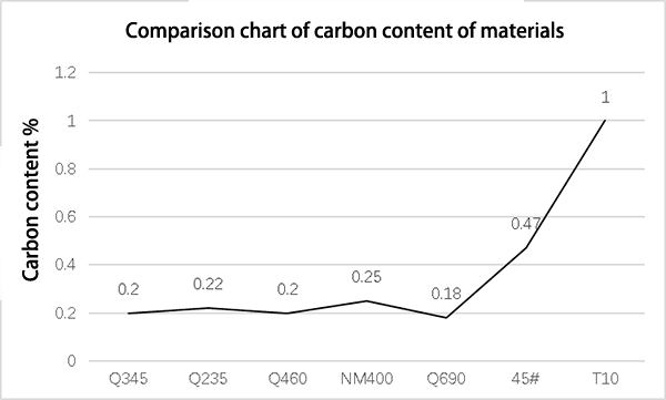
Fig. 7 – Comparative Chart of the Carbon Content of Materials
When initially comparing Q235 and Q345B materials, it was found that the manganese (Mn) element content has a minimal impact on the actual cutting effect and can be disregarded.
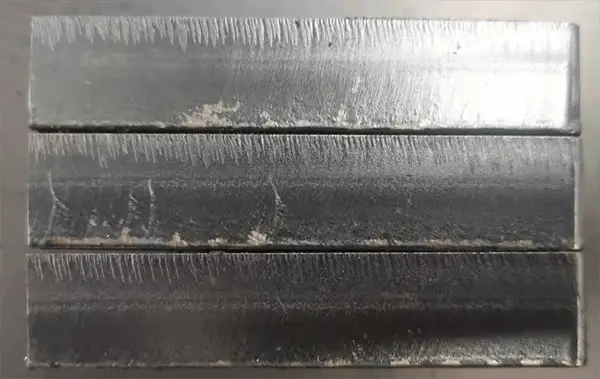
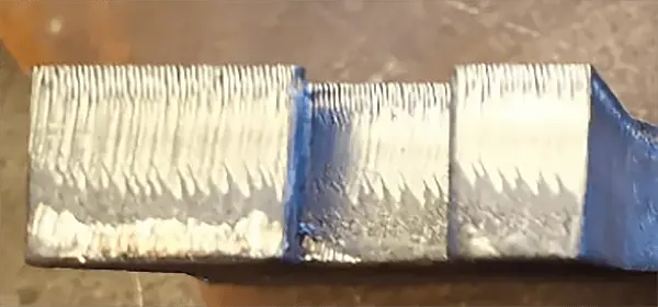
Figure 8 shows the actual cutting effect of the three materials with the same thickness. The results show that the surface of Q235 is shiny with low roughness, the surface of 45# is rough with a significantly thicker oxide film on the bottom, and the surface of T10 is the roughest with the thickest oxide film.
From the actual test results, it can be concluded that the carbon content in the material has a notable impact on the cutting effect. As the carbon content increases, the number of pores on the cutting surface increases, the thickness of the surface oxide film becomes thicker, and the surface roughness increases.

Fig. 8-Q235-30kw-40mm (left), 45# – 30kw-40mm (middle), T10-30kw (right)
5) Ni element content analysis
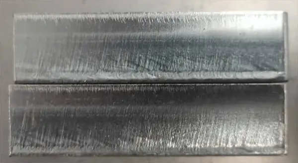
Table 7 displays the types and contents of chemical elements in materials Q235 and Q460. The difference in the content of the element nickel (Ni) between the two materials is evident.
Consequently, cutting tests were carried out on plates of the same thickness for both materials. Actual cut quality results are shown in Figure 10.
There is no noticeable difference in surface striations, oxide film thickness and surface roughness.
Based on these results, it can be concluded that in conventional low-carbon steel, the nickel content does not have a significant impact on the cutting quality of high-power lasers.
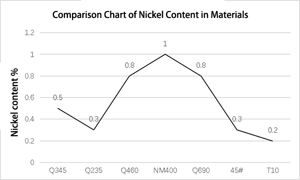
Fig. 9 – Comparative Chart of Nickel Content in Materials
Table 7 Comparison of Ni Elements
| Chemical element/% | Board type | Q235 | Q460 |
| W | 0.22 | 0.2 | |
| Mn | 0.65 | 1.8 | |
| Yes | 0.3 | 0.6 | |
| s | 0.05 | 0.03 | |
| P | 0.045 | 0.03 | |
| Cr | 0.3 | 0.3 | |
| No | 0.3 | 0.8 | |
| Ass | 0.3 | / | |
| Mo | / | / | |
| No. | / | 0.11 | |
| V | / | 0.2 | |
| You | / | 0.2 | |
| AI | / | / | |
| B | / | / | |

Q460-20mm-20KW

Q235-20mm-20KW
Figure 10
6) Content analysis of the Cr element
When comparing the content of elements in the plate, it is observed that the content of the element chromium (Cr) in materials NM400 and Q690 is significantly higher than in other materials, as illustrated in Figure 4.2-5.
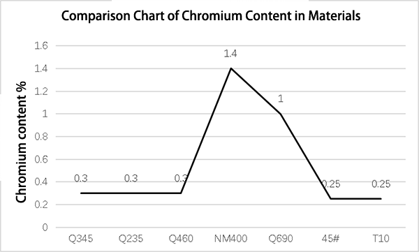
Fig. 11 Comparison chart of chromium content in materials
During the laser cutting process, most of the elements on the board will oxidize with the auxiliary gas, oxygen, and release a large amount of heat when the laser releases heat. This results in the formation of a significant heat-affected zone on the surface of the board.
In this heat-affected zone, the chromium (Cr) in the plate will oxidize with oxygen and produce dense Cr 2 Ó 3 and other oxides, which will increase with local temperature. The oxide gradually grows and forms a cluster-like granular structure, as shown in Figure 12.
Over time, a Cr 2 Ó 3 oxide film with high surface tension and less prone to cracking on the cutting surface of the metal, which prevents the oxidation reaction between the elements below the Cr 2 Ó 3 oxidation and O 2 (as per shown in Figure 13). This results in significantly low surface roughness on the bottom of the NM400 and Q690 cutting surfaces (as seen in Figure 14).
It can be concluded that the cutting effect worsens with increasing Cr content in the material and the oxide film at the bottom of the sample becomes thicker.
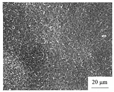

Figure 12 – Phase diagram of grouped particles
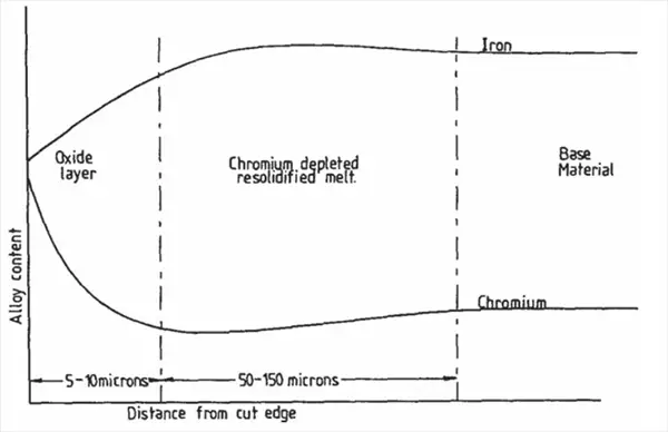
Fig. 13 – Laser Cutting Surface Oxide Layer Analysis Diagram
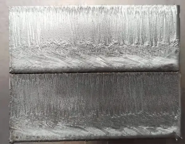
Cutting effect display 20mm NM400
Cutting Effect Display 20mm Q690
Figure 14
2.3 Analysis of the heat-affected zone
It is understood that the quality of laser cutting is related to the heat-affected zone on the surface of the sheet to be cut. When the heat-affected zone is not controlled, it can cause distortions, cracks, brittleness, etc. on the surface of the cut board.
According to the data comparison in Figure 15, it is known that the laser cutting power is the main factor affecting the width of the cutting slit, and the cutting speed is the main factor affecting the flutes and roughness of the cutting surface.
Therefore, in laser cutting, it is recommended to adjust the process parameters as much as possible to minimize the area of the heat-affected zone on the board surface in order to reduce deformation and enrichment of components.


Fig. 15 – Influence of power and speed on cutting and cutting surface
During the actual testing process, the cutting process parameters were optimized to ensure smooth cutting surfaces and free falling of samples of different types and thicknesses.
Under the same cutting power, there is no substantial difference in the width of the slits between different types and with the same thickness.
As a result, the heat-affected zone area of materials with the same thickness is similar under the same power, having only a minor impact on the actual surface roughness and can be disregarded.
3. Conclusion
Factors that influence the cutting quality of carbon steel through oxygen cutting include alloy composition, material microstructure, thermal conductivity, melting point, and boiling point.
Metals with a high carbon content typically have high melting points, making them difficult to melt, leading to increased cutting and drilling time.
This results in a wider cut and a heat-affected zone on the expanded surface, causing unstable cut quality.
Related Reading: Things You Should Know About Laser Cutting
Furthermore, a high content of alloy composition increases the viscosity of the liquid metal and increases the proportion of spatter and slag, placing greater demands on adjusting the laser power and air blowing pressure during processing.
Related Reading: How to Select Fiber Laser Cutting Machine Power?
The above tests show that when oxygen is used as an auxiliary gas, the cutting surface effect worsens and the surface roughness increases significantly as the content of C and Cr elements in the material increases. On the other hand, when air is used as an auxiliary gas, the cutting effect remains practically unchanged under the same thickness and power.
To ensure cutting quality and efficiency, the types of auxiliary gas recommended for different cutting powers and materials are listed in the following table:
- Impact of carbon content:
Under the same laser power, as the carbon content increases, the cutting speed gradually decreases, while the sample surface becomes rougher, the oxide film becomes thicker, and the overall effect deteriorates, leading to a reduction in the thickness limit of laser cutting plates.
- Impact of Chromium Content:
As the chromium content increases, the oxide film on the bottom of the sample surface builds up and visibly thickens, causing the cut surface to become rough from top to bottom.
- Impact of silicon content:
When the silicon content in the material exceeds 0.25%, the cutting speed decreases significantly with increasing silicon content, and slag appears at the bottom of the cutting sample.
- Nickel content:
Nickel content has little effect on the quality of high-power laser cutting.
- Impact of manganese and sulfur content:
When the manganese and sulfur content in the material is 0.5% and 0.04% respectively, the slag at the bottom of the cut gradually increases as the thickness of the plate increases.