In the previous tutorial, we learned how the ATtiny85 communicates serially with the HC05 Bluetooth module and sends/receives commands from the Bluetooth smartphone
This tutorial also involves the function of the HC05 Bluetooth module. But instead of receiving commands from a smartphone, it sends sensor data values to the smartphone. The sensor is connected to an analog input pin on the ATtiny85. It can be any analog sensor like LDR or temperature sensor (LM35), soil moisture sensor, etc. ATtiny85 will read the analog voltage output from the sensor, convert it to a digital value and transmit it to the smartphone using the HC05 module. Therefore, it becomes a wireless sensor data transmitter. Let's see how this is done.
Suppose you are not following this tutorial series from the beginning. In this case, you will have to follow the following two tutorials that explain and demonstrate how to work with ATtiny85 and a step-by-step guide to building a “hello world” (blinking LED) application.
How to work with ATtiny85
LED blinking using ATtiny85
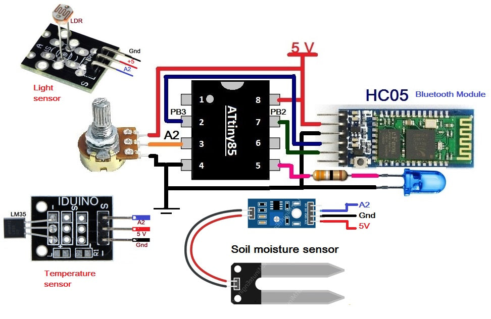
Circuit Diagram
![]()
Circuit Connections
The circuit is built using just 3-4 components, HC05 module, an LED, ATtiny85 and a three-pin sensor module (any sensor module shown here like a potentiometer, LM35 temperature sensor module, LDR sensor module and humidity sensor module). ground) . The HC05 (Bluetooth module) has four interface pins (1) Vcc (2) Gnd (3) Tx and (4) Rx. The Tx pin is connected to PB2 (pin 7) and the Rx pin is connected to PB3 (pin 2). Vcc pin is connected with 5V and GND pin is connected with pin 4 connected to ground. The sensor module has three interface pins (1) Vcc (2) and (3) Signal. The Vcc pin is connected with 5V and the GND pin is connected to pin 4 of the ATtiny85. The signal pin which is the analog output of the sensor is connected to the analog input pin A2 of the ATtiny85. The circuit above shows a 5V supply.
Note: Almost all analog sensors have a three-pin interface. A potentiometer is connected to this circuit, but any other sensor that operates at 5V can also be connected in place of this potentiometer.
Circuit operation
- When 5V power is supplied to the circuit, the HC05 module will begin blinking to indicate that it is searching for another Bluetooth device to pair (connect) with.
- The person reading the sensor data will first open an Android application with Bluetooth communication capability on their smartphone. (You can find many of these apps in the Google Play Store. Just search “Bluetooth Control for Arduino”). This app will search and pair with the HC05 module (to pair 1st time, it must enter the Bluetooth password for the HC05 module, which by default is 1234). When the smartphone is connected to the HC05 module, its blinking rate will be slow
- Now the phone's Android app is ready to receive sensor data
- ATtiny85 will read the sensor's analog voltage output and convert it to digital
- It then transmits this value to the smartphone via the HC05 module. It just sends this value serially to the HC05 module, and the module will later transmit it wirelessly to the smartphone
- the Android app uses the phone's Bluetooth and gets the sensor data and displays it on the smartphone screen
Program
The program is written in Arduino IDE software using the C programming language. It is compiled and a HEX file is created that is downloaded to the ATtiny85's internal FLASH
Program logic
There are four different programs for four different types of sensors. Mainly the program is the same, but there are few changes in the shipping data value formats.
Initially, the program sends a message to the user's smartphone informing that Bluetooth is connected to the HC05 and sends sensor data.
Program for Potentiometer
Program for LDR
Program for LM35
Soil Moisture Program
The program then continuously reads the sensor data, converts it into the appropriate format, and then serially transmits it to the phone. It blinks the LED whenever new sensor data is transmitted and this repeats every 1 second.
This is the last tutorial in this series. In this series of tutorials, we learn about the ATtiny85 microcontroller from the basic level to the application level and interesting applications.
You can also build any small and simple application using an ATtiny85 microcontroller, especially when there are fewer I/O pins and you want to build a tiny and compact device with a small form factor.