LoRa (Long Range) technology ensures reliable long-range communication between a node and a gateway, providing low power usage for devices over the long term. This article provides an explanation of LoRa node-to-gateway communication while presenting a node equipped with two buttons to control the flags. These buttons allow users to enable or disable specific actions associated with each button and update the status on the gateway.
From home automation to industrial monitoring, this enhanced LoRa communication configuration presents diverse possibilities for Internet of Things (IoT) deployments.
This tutorial will cover hardware configuration, protocol selection, and gateway configuration, facilitating real-time data transmission and visualization.
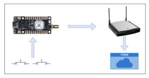
A block diagram of LoRa node-to-gateway communication.
Abstract
Here’s what we’ll cover…
1. How to upload LoRa code to LoRa E5 Mini-Board
2. Circuit diagram for connecting an ST-Link and buttons to the LoRa E5 Mini-Board
3. How to configure an end node on the gateway
4. The program flow or algorithm with an explanation
Requirements
1. Make sure the LoRa gateway is already installed as shown in this article
2. STM32Cube IDE must be installed on your PC
3. The Seed Studio LoRa E5 Mini Card
4. The original ST-Link V2 programmer
5. A tactile switch and some basic welding knowledge
Compiling the code
1. Download the code and extract it
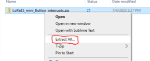
Download the code and extract it from the folder.
2. Open the folder and double click on “.project”
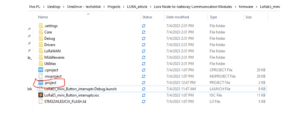
Open the project file in the STM32Cube IDE.
3. The project will be listed in the 'Project Explorer' tab on the left of the STM32CUBE IDE. Select the project and click the hammer icon in the top bar to compile the code.
Compiling the code in the STM32CUBE IDE.
4. After compiling the code, there should not be any error as shown in the image below. If there is an error message, follow the steps again to ensure success.
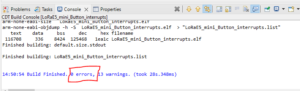
Build successful with zero errors.
Loading the code
1. Locating a genuine ST-Link V2 is necessary for proper updating of the LoRa code, as clone variants of ST-Link are often not compatible. This means that it is essential to recognize the original ST-Link. A reliable method of identification involves examining the hardware components.
After thorough analysis, a genuine ST-Link V2 has an STM chip, indicating authenticity. Clones are typically imported from China and have a slightly different appearance.
This project requires a smooth “flashing process”, which occurs reliably with a genuine ST-Link with STM chip (see image below). Knowing the difference will ensure compatibility and proper programming.
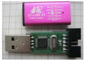
An original ST-Link V2.
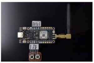
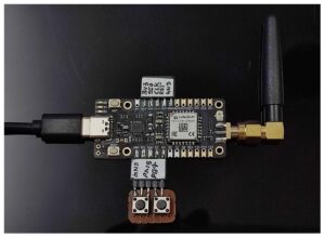
2. Connect five wires to the LoRa E5 Mini Board as shown in the image below, including 3V3, SWDIO, SWCLK, RST and GND.
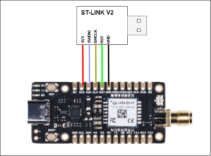
The ST-Link connection between the ST-Link V2 and the LoRa-E5.
3. Go back to the STM32 Cube IDE and click 'Play; button as shown below to upload the code.
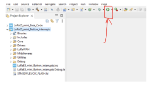
Loading code with 'Play' button in STM32 Cube IDE.
4. You should receive the message “Download verified successfully”.
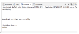
You should receive the message “Download verified successfully“ before proceeding.
Connecting the buttons
Connect the two tact switches as shown in this circuit diagram:
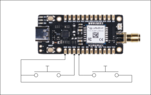
The circuit diagram for the tactile switches.
The connection between the tactile button and the LoRa-5E.
Adding a device to the gateway
1. If there is no device profile, add one. If you already have one, this same profile can be used for multiple nodes.
2. To add a profile, open ChirpStack and go to 'Device Profiles'.
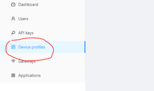
The 'Device Profiles' in the Chirpstack dashboard.
3. Click 'Add Device Profile'.
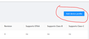
The 'Add Device Profile' button.
4. Fill in the general information and click 'Submit'.
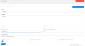
General LoRa profile information to fill out.
5. Turn OTAA off because the device will work in ABP mode. Fill in the RX3 data rate details and frequency.
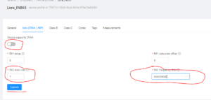
The junction (OTAA/ABP) in the LoRa general profile window… select ABP.
6. Activate Class C mode as shown below.
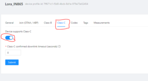
Enable Class C in the general LoRa profile.
7. Then add 'Applications' which contains all devices.
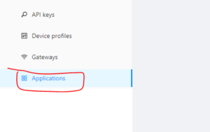
LoRa 'Application' window.
8. Click 'Add Applications'.
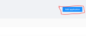
Click 'Add LoRa App'.
9. Fill in the registration details as indicated below in the image.
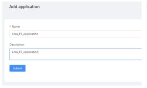
Complete the 'Registration' form.
10. Click on the application that was just created and then click on the 'Add Device' button. This process must be done whenever a new device is added.
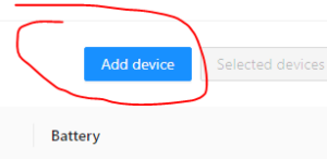
Click 'Add Device'.
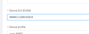
11. Start filling in the details as shown below. You'll need to find the device's EUI, which we'll cover in the next step.
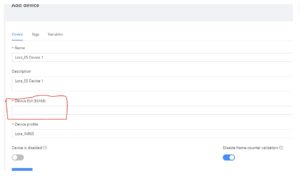
Device window with missing device EUI information.
Finding EUI and KEYs
1. To find the EUI device and keys, connect the device to a PC via USB cable.
USB connection between the device and a PC.
2. Open any serial terminal (we are using Arduino) and select the device port. Open the Serial Terminal with a baud rate of 115200. Press the 'Reset' button to see the Keys.
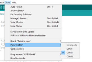
Arduino Serial Terminal Window… used to find the Keys.
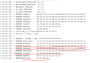
The EUI and key information.
3. Copy the EUI device from the serial terminal and paste it into ChirpStack Add the device section as shown in the image below.
The device's EUI data.
4. Go to the 'Activation' section and fill in the device address, AppSkey and Network S key, which you can get from the Serial Terminal.
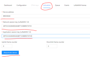
The 'Activation' of the device.
Receiving data
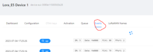
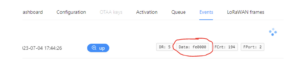
1. To receive data, go to the events section where there is data received every 10 seconds.
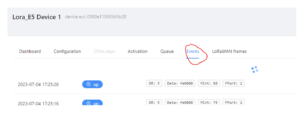
Device events received every 10 seconds.
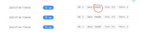
2. Data is in hexadecimal format. Sends the battery level, as well as the status of Button1 and Button2, in hexadecimal.
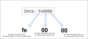
The hexadecimal data format.
3. When Button1 is pressed, the Button1 flag will be HIGH in the following data (just click once with the mouse without holding it down).
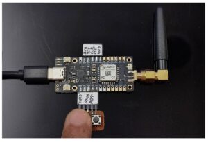
This is the LoRa-5 connected to the tactical buttons when Button1 is clicked.
When Button1 is pressed, the flag will be HIGH.
4. When Button2 is pressed, the Button2 flag will be HIGH in the following data.
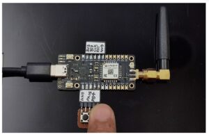
This is the LoRa-5 connected to the tactical buttons when Button2 is clicked.
When Button2 is pressed, the flag will be HIGH.
5. When both buttons are pressed, the flag will be zero.
When both buttons are clicked, the flag will be zero.
Code algorithm
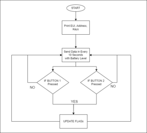
The algorithm.
Code Explanation
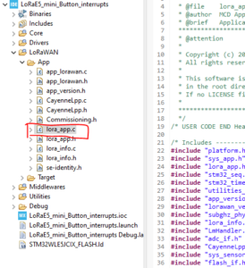
1. LoRa-based STM32 code is slightly different from typical codes. The main.c file starts the process to run lora_app.c as the main file. So, open the lora_app.c which contains the code.
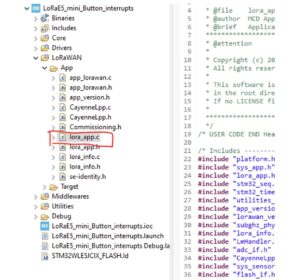
The lora_app.c as main file.
2. There's a lot going on in the code, but let's review what's relevant to this tutorial. The condition below starts a timer, which calls the OnTxTimer Event function that sends data to the gateway. The default time is 10 seconds, which can be changed by initializing TxPeriodicity in milliseconds. The image below removes the APP_TX_DUTYCYCLE and puts the required time delay in milliseconds.
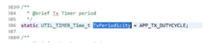
Explains the OnTxTimerEvent function to send data on the LoRa gateway.
This function handles all interrupts that occur on the interrupt pins. There is a 100 millisecond delay for debugging purposes.
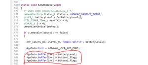
The SendTxData function containing a buffer to send data to LoRa.
Integrating smart meters
Smart meters with pulse sensors can be seamlessly integrated into the above code. Pulse sensors generate pulses whenever the meter reading increases, acting as if the button stops in this tutorial. By configuring a microcontroller (MCU) to recognize these pulses as interruptions, a user can effectively track meter readings in real time.
Whenever a pulse is received by the interrupt pin, the MCU will increment the meter reading and store it as a variable. The code can then be programmed to send these readings to the gateway at regular intervals, such as every 10 seconds. The transmission frequency can be adjusted to meet specific application requirements.
This integration improves the functionality of smart meters, enabling accurate and automated tracking of energy consumption. With real-time readings, utilities can efficiently monitor usage, identify patterns and optimize energy distribution. The versatile code can be adjusted for different pulse sensor configurations, so it can work with many smart meter designs.