
In an alternating current, the voltage changes polarity from positive voltage to negative voltage and vice versa over time, and the current oscillates back and forth accordingly. The serial shape of an AC power supply follows the scientific shape of a “sine wave,” often called a sine wave shape. A sinusoidal voltage is therefore described as V
Using pure resistors in AC circuits with tiny values of capacitance or inductance, the same principles of Ohm's law, and the same circuit rules for power, voltage, and current applications as resistance DC circuits, the only difference now is the use of Instant “Peak” or “RMS” peak values.
Resistor color coding and resistance calculation
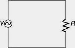
When operating with AC voltage and current, it is common practice to only use the RMS value to avoid confusion. Additionally, the representation symbol used to represent an AC power supply is that of a “wavy line” as a critical battery representation for DC power, shown below.
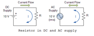
Resistors are “passive” devices that neither generate nor consume electrical energy, but rather convert it into heat. In a DC circuit, the linear relationship between voltage and current across a resistor is called resistance. In an AC circuit, however, this voltage/current relationship depends on the frequency and phase angle (φ) of the source. Therefore, when a resistor is used in an AC circuit, the term impedance, symbol Z, is normally used and we say that AC impedance = DC resistance, R = Z.
It is important to note that when a resistor is used in AC circuits, unlike capacitors and inductors, it can always have the same resistance value regardless of the frequency of availability from DC to very high frequencies.
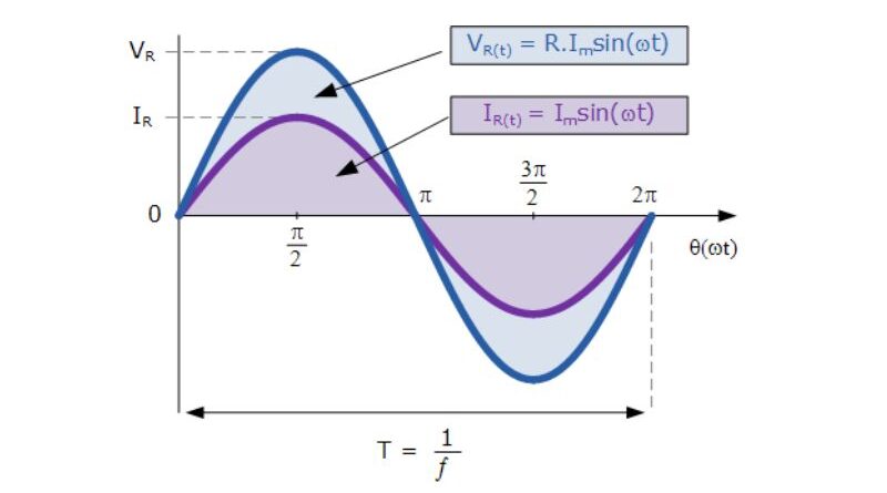
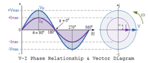
With resistance in AC circuits, the movement of current flowing through them has no effect on the behavior of the resistance and can therefore increase and decrease as the voltage increases and decreases. The voltage and current reach the maximum value, fall from zero and touch the minimum at the same time. This means that they rise and fall at the same time and are equal, that is, “in phase”, as shown below.

We can see that at any point on the horizontal axis, the instantaneous voltage and current are in phase; therefore the voltage reaches most of its values at the same time; that is, its phase θ is 0 Ó . Then these instantaneous voltage and current values are compared to determine the resistance value according to Ohm's law. Let us consider the following circuit which consists of an AC power supply and a resistor.
The fast (instantaneous) voltage across the resistor VR corresponds to the supply voltage V T, and is stated as follows:
VR = V Max Sin ωt
The instantaneous current flowing in the resistors is therefore:
EU R =V R /R
EU R = (v Max Sinωt)/R
RI = I Max Sin ωt
For example, the voltage across a resistor is given as VR = IR, and the fast voltage across the above resistor can be given as:
v R =I Max Sin ωt
In a strictly resistive series AC circuit, the total voltage that drops across the resistor is shifted to meet the total voltage of the circuit rather than all the voltages that are in phase with each other. In a strictly resistive parallel AC circuit, all the individual branch currents are shifted to find the total circuit current because all the branch currents are in phase with each other.
Electric charge and current
Since the phase φ between voltage and therefore current is zero for resistance in an alternating current circuit, the PF factor of the circuit is assumed to be cos0. Oh =1. The power within the stroke at any given time is determined by the product of voltage and current at that time.
The power consumed by the circuit (P) is given as follows: P=V Effective value ΙcosΦ in watts. However, as cosΦ=1 in a strictly resistive circuit, the energy consumed is simply given as P=V Effective value I similar to Ohm's law.
This gives the “power” waveform as a series of positive pulses at the bottom. The resulting power is positive when the voltage and current are in the positive half of the cycles. If the voltage and current are negative, multiplying the two negative values results in a positive power pulse.
Role and effects of resistance in alternating current circuits
Resistance in an AC circuit leads to impedance, which combines resistance and reactance. It resists current flow, converts electrical energy into heat, and affects the overall performance of the circuit. By studying the principles of AC circuits, including Ohm's law and phasor representation, we can better understand how resistance affects the behavior of AC systems.
Additionally, this article examines the effects of resistance on various AC circuit parameters. It examines the relationship between resistance and power loss, voltage and current waveforms, and the concept of power factor. Understanding these effects allows engineers and designers to optimize circuit performance, minimize power losses, and ensure efficient power transmission.
By demystifying resistance in AC circuits, this article gives readers the knowledge to navigate the complexities of electrical systems. Whether analyzing power distribution networks, designing electrical devices, or troubleshooting circuits, it is essential to have a clear understanding of resistance in AC circuits. Join us as we dive into the fascinating world of resistance and reveal its role and effects in AC circuits.