Vehicle tracking systems are a necessity for today's travelers. These systems are essential for keeping personal vehicles safe from theft and theft. Vehicle Tracking Systems are only possible to design by enabling them with internet. In this project, a simple vehicle tracking system is designed that will continuously update the vehicle's current location to a personalized web page.
Vehicle tracking systems are designed to track the movement of a vehicle from one location at any given time. This system is equipped with a GPS receiver that maintains the GPS location of the device. The GPS location of the device tracked by the GPS sensor is sent to a cloud server or cloud service with the help of a controller. This project is a simple implementation of this system on one of the most popular prototyping boards – Arduino UNO.
It is assumed that the reader has gone through the project on how to start using the Arduino and the LCD interface with the Arduino. The vehicle tracking device designed here is an IoT device. It has Arduino interfaced with Neo-6M GPS Module, a character LCD and ESP8266 Wi-Fi modem. The Arduino receives the device's location from the GPS receiver and displays it on the character LCD. As the device finds a data connection through Wi-Fi, such as a smartphone's Wi-Fi hotspot, it sends the current GPS location to a personalized web page. The web page shows the location of the device with the help of Google Maps.
This simple vehicle tracking device is easy to design, implement and can be installed in any vehicle. It tracks the vehicle in which it is installed in real time. The GPS data that this device displays and sends to the remote page is the geographic coordinates (latitude and longitude) of the device.
The Arduino Sketch manages the device's functionalities such as obtaining GPS location, displaying it on the LCD module, connecting to a Wi-Fi access point and sending the GPS data to a page generated in real time. Arduino sketch is written, compiled and uploaded with the help of Arduino IDE.

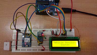
Figure 1: IoT vehicle tracking device prototype based on Arduino and ESP8266
Required components –

Fig. 2: List of components used in the design of Arduino and ESP8266 based IoT vehicle tracking device
Block diagram –

Fig. 3: Block diagram of IoT vehicle tracking device based on Arduino and ESP8266
Circuit Connections –
The Arduino-based vehicle tracking system designed here is an IoT device. It is designed by connecting GPS module, character LCD and ESP8266 Wi-Fi modem to Arduino UNO. The NEO-6M GPS module is used to obtain the geographic coordinates of the location. The ESP module is used to update the location of the vehicle to the web server which can be tracked through Google Maps, where the exact position of the vehicle's movement can be tracked.

Fig. 4: Image showing circuit connections of Arduino and ESP8266 based IoT vehicle tracking device
The Arduino based vehicle tracking IoT device has the following components and circuit connections –
Power source – The Arduino UNO can be powered by a USB socket. USB power supplies are available in most cars. Even bicycles can be modified to have a USB power source from the vehicle's battery. The GPS module and character LCD in the circuit draw power from the Arduino's 5V DC source, while the ESP8266 Wi-Fi modem draws power from the Arduino's 3.3V DC source.
Arduino UNO – The Arduino UNO is an ATmega328 based microcontroller board. The board comes with an integrated Arduino bootloader. It has 14 GPIO pins, 6 PWM pins, 6 analog inputs and integrated UART, SPI and TWI interfaces, an integrated resonator, a reset button and holes for mounting pin connectors. While programming the board, it can be connected to the PC using the USB port and the board can run on USB power. The Arduino UNO has 32 Kb of Flash memory, 1 Kb of EEPROM and 2 Kb of SRAM. The board can be connected to different Arduino Shields for Ethernet, Bluetooth, Wi-Fi, Zigbee or cellular network connectivity and can be connected to most IoT platforms. The ATmega328 controller has the following pin configuration –

Fig. 5: Table listing the Arduino Uno pin configuration

Fig. 6: Table listing the Arduino Uno pin configuration
In this project, 6 GPIO pins of Arduino are used to interface character LCD, 2 GPIO pins are used to provide serial communication with ESP8266 modem using software serial and two GPIO pins are used for communication serial with the GPS module.
ESP8266 Wi-Fi Modem – ESP8266 Wi-Fi Module is used to connect the Arduino board to a Wi-Fi access point so that it can access the cloud server and update GPS data to the server. It is an independent SOC with integrated TCP/IP protocol stack that can access a Wi-Fi network. The ESP8266 is capable of hosting an application or offloading all Wi-Fi network functions from another application processor. Each ESP8266 module comes pre-programmed with AT command set firmware. The module is available in two models – ESP-01 and ESP-12. The ESP-12 has 16 pins available for interfacing, while the ESP-01 only has 8 pins available for use. The ESP-12 has the following pin configuration –

Fig. 7: Table listing the pin configuration of the ESP8266 ESP-12 Wi-Fi modem
The ESP-01 model is used in the project. The ESP-01 model has the following pin configuration –

Fig. 8: Table listing the pin configuration of the ESP8266 ESP-01 Wi-Fi modem
The module's RESET and VCC pins are connected to the Arduino's 3.3V DC while the Ground pin is connected to the common ground. The Tx and Rx pins of the module are connected to pins 10 and 11 of the Arduino UNO respectively where the Arduino pins are configured as serial receiver and transmitter respectively using serial software library.
16X2 LCD – The 16X2 LCD display is connected to the Arduino board by connecting its data pins DB4 to DB7 with pins 8 to 5 of the Arduino board. The RS and E pins of the LCD are connected to pins 13 and 12 of the Arduino board respectively. LCD RW pin is grounded.

Fig. 9: Table listing the circuit connections between the LCD and the Arduino Uno
The open source standard library for interfacing LCD with Arduino board is used in the project. The library works as expected and does not need any changes or modifications.
GPS Module – The GPS module used in this project is the Neo 6M. It is a standalone GPS module with 50-channel u-blox 6 positioning engine that boasts a Time-To-First-Fix (TTFF) of less than 1 second. The dedicated acquisition engine, with 2 million correlates, is capable of massively parallel time/frequency space searches, allowing it to find satellites instantly. Innovative design and technology suppress sources of interference and mitigate multipath effects, giving NEO-6 GPS receivers excellent navigation performance even in the most challenging environments. It has UART port for data transfer. The SOC on the module is a 24-pin chip with the following pin configuration –

Fig. 10: Table listing the Neo 6M GPS chip pin configuration

Fig. 11: Table listing the Neo 6M GPS chip pin configuration
The GPS module is connected to the Arduino UNO as per the following table –

Fig. 12: Table listing the circuit connections between the GPS module and the Arduino Uno
Arduino pins 2 and 3 are configured as software serial receiver and transmitter respectively using the software serial library.
How the circuit works –
When the Arduino-based IoT device is powered on, some initial messages are displayed on the character LCD and it starts reading the GPS data from the Neo-6M module. First, the local server IP must be loaded into the web page that will initially be displayed on the Arduino serial monitor or LCD display. GPS starts getting the geographical coordinates of the location, where the GPS module gets the location update every 27 seconds and updates to the web server with the help of ESP Wi-Fi module. The device starts searching for an access point Wi-Fi. If a Wi-Fi hotspot is available, the Arduino obtains the IP address if necessary and connects to the Wi-Fi point. The Wi-Fi hotspot name and password are encoded in the sketch of Arduino. Initializing the Wi-Fi connection is done within the Arduino sketch setup function, which is executed as soon as the board is turned on.
Wi-Fi connection configuration is performed by passing AT commands to the ESP8266 Wi-Fi modem. The modem is connected to the GPIO pins of the Arduino which are configured as UART transmitter and receiver pins using the software serial library. Wi-Fi is initialized by passing the following AT commands to the ESP module –
AT: This command is passed to check if the modem is working properly.
AT+CWMODE=3: This command is passed to set the Wi-Fi mode for both AP mode and Station mode.
AT+CWQAP: This command is passed to disconnect from any AP (Access Point) if the modem is connected.
AT+RST: This command is passed to restart the modem.
After rebooting, the modem checks the IP addresses of available access points. The ESP modem can connect to the access point whose SSID and password are encoded in Arduino Sketch. The following AT command is passed to connect to the access point –
AT+CWJAP
Once the modem is connected to an access point, it obtains the IP address by running the following command –
AT+CIFSR: This command is used to obtain the IP address of the ESP module as a client.
The IP address is stored in a string and recognized by the Arduino board. Now the following AT commands are passed to the ESP module – AT+CIPMUX=1: This command is passed to enable multiple connections.
AT+CIPSERVER=1.80: This command is passed to create a server on port 80.
The Arduino reads the latitude and longitude from the GPS module. GPS data is encapsulated in appropriately formatted strings and stored in variables. They are displayed on the character LCD and sent to the remote server (local server in this case) when Wi-Fi connection is available. Data is updated every 27 seconds and current stored data is updated to the local server as the Wi-Fi connection is configured. Local server is a PC or laptop connected to the same Wi-Fi access point and running localhost. A web page is created by Arduino Sketch and sent with the updated GPS data to the local server. On the web server, the location of the moving vehicle can be viewed by Google Maps. The device here connects to localhost. To connect to a hosted website or web page, port forwarding must be done on the ESP8266 modem.
Programming guide –
Arduino sketching starts with importing standard libraries like SoftwareSerial.h and LiquidCrystal.h. LiquidCrystal.h is used to manage data communication between the LCD module and Arduino. SoftwareSerial.h is used to configure Arduino pins as serial transmitter and receiver to perform serial communication with GPS module and ESP8266 modem. Some variables are declared to contain GPS data and messages, Wi-Fi access point IP address, and web page HTML content.
.

Fig. 13: Screenshot of the Arduino code used to initialize the IoT Vehicle Tracking device
The setup function is called in which the baud rate for serial communication with the Wi-Fi modem is defined. Wi-Fi mode and network connectivity are established using AT commands with some delays. The delay must be given according to the time it takes to connect to the network by calling the wifi_init function. The GPS module is initialized and the coordinates are read using the get_gps function.

Fig. 14: Screenshot of Arduino code configuration function used in vehicle tracking IoT device
The loop function is called and runs infinitely. In this function, the get_gps function is called to read the geographic coordinates of the location. Functions are called to create HTML content for the web page with updated GPS location and send the web page to the local web server.

Fig. 15: Mani Loop screenshot of Arduino code used in IoT vehicle tracking device
Check out the Arduino Sketch in the code section to try it out. This is a simple GPS device for vehicle tracking. The Arduino code can be modified to connect to any web page or website. It is a low-cost and easy to implement IoT project.
Project source code
### //Program to #include#include SoftwareSerial Serial1(2,3); //make RX arduino line is pin 2, make TX arduino line is pin 3. SoftwareSerial gps(10,11); LiquidCrystal lcd(13,12,9,8,7,6); boolean No_IP=false; String IP=""; String webpage=""; int i=0,k=0; int gps_status=0; String place=" 1. Name: (ENTER UR NAME) "; String num = " 2.Vehicle No: IND001
"; String cordinat="Coordinates:
"; String latitude=""; String logitude=""; String gpsString=""; char *test="$GPGGA"; void setup { Serial1.begin(9600); Serial.begin(9600); lcd.begin(16,2); lcd.print("Vehicle Monitoring"); lcd.setCursor(0,1); lcd.print(" System "); delay(2000); lcd.clear; lcd.print("Connecting...."); delay(1000); connect_wifi("AT",1000); connect_wifi("AT+CWMODE=3",1000); connect_wifi("AT+CWQAP",1000); connect_wifi("AT+RST",5000); FindIP(5000); if(!No_IP) { Serial.println("Connecting Wifi...."); connect_wifi("AT+CWJAP="(ENTER UR SSID NAME) ","(ENTER THE PASSWORD)"",7000); //AT+CWJAP=”wifi_username”, “wifi_password” } else { } Serial.println("Wifi Connected"); lcd.clear; lcd.print("WIFI Connected"); delay(2000); lcd.clear; lcd.setCursor(5,0); lcd.print("IP"); lcd.setCursor(3,1); lcd.print("ADDRESS"); ip_add; delay(2000); connect_wifi("AT+CIPMUX=1",100); connect_wifi("AT+CIPSERVER=1,80",100); Serial1.end; lcd.clear; lcd.print("GPS DATA"); delay(2000); gps.begin(9600); get_gps; coordinate_display; gps.end; Serial1.begin(9600); } void loop { k=0; Serial.println("Please Refresh Ur Page"); while(k<1000) { k++; while(Serial1.available ) { if(Serial1.find("0,CONNECT")) { Serial1.end; gps.begin(9600); get_gps; gps.end; Serial1.begin(9600); Serial1.flush; Serial.println("Start Printing"); Send ; coordinate_display; Serial.println("Done Printing"); delay(5000); lcd.clear; lcd.print("System Ready"); delay(1000); k=1200; break; } } delay(1); } } void FindIP(int t1) { int t2=millis ; while(t2+t1>millis ) { while(Serial1.available >0) { if(Serial1.find("WIFI GOT IP")) { No_IP=true; } } } } void ip_add { IP=""; char ch=0; while(1) { Serial1.println("AT+CIFSR"); while(Serial1.available >0) { if(Serial1.find("STAIP,"")) { delay(1000); Serial.print("IP Address:"); while(Serial1.available >0) { ch=Serial1.read ; if(ch=='+') break; IP+=ch; } } if(ch=='+') break; } if(ch=='+') break; delay(1000); } lcd.clear; lcd.print(IP); lcd.setCursor(0,1); lcd.print("Port: 80"); Serial.print(IP); Serial.print("Port:"); Serial.println(80); delay(1000); } void connect_wifi(String cmd, int t) { int temp=0,i=0; while(1) { Serial.println(cmd); Serial1.println(cmd); while(Serial1.available >0) { if(Serial1.find("OK")) { i=8; } } delay if(i>5) break; i++; } if(i==8) { Serial.println("OK"); } else { Serial.println("Error"); } delay(1000); } void gps_Function { gpsString=""; while(1) { while (gps.available >0) //Serial incoming data from GPS { char inChar = (char)gps.read; gpsString+= inChar; //store incoming data from GPS to temporary string str i++; if (i < 7) { if(gpsString(i-1) != test(i-1)) //check for right string { i=0; gpsString=""; } } if(inChar=='r') { if(i>65) { gps_status=1; break; } else { i=0; } } } if(gps_status) break; } } void get_gps { gps_status=0; int x=0; while(gps_status==0) { gps_Function; int str_lenth=i; latitude=""; logitude=""; coordinate2dec; i=0;x=0; str_lenth=0; } } void coordinate_display { lcd.clear; lcd.print("LATITUTE:"); lcd.print(latitude); lcd.setCursor(0,1); lcd.print("LONGITUTE:"); lcd.print(logitude); Serial.print("Latitude:"); Serial.println(latitude); Serial.print("Longitude:"); Serial.println(logitude); } void coordinate2dec { String lat_degree=""; for(i=18;i<20;i++) //extract latitude from string lat_degree+=gpsString(i); String lat_minute=""; for(i=20;i<28;i++) lat_minute+=gpsString(i); String long_degree=""; for(i=30;i<33;i++) //extract longitude from string long_degree+=gpsString(i); String long_minute=""; for(i=33;i<41;i++) long_minute+=gpsString(i); float minut= lat_minut.toFloat; minute=minute/60; float degree=lat_degree.toFloat ; latitude=degree+minute; minute= long_minute.toFloat ; minute=minute/60; degree=long_degree.toFloat ; logitude=degree+minute; } void send { webpage = "Welcome to Engineers Garage
"; webpage+=place; webpage+=num; webpage+=cordinat; webpage+="Latitude:"; webpage+=latitude; webpage+="
"; webpage+="Longitude:"; webpage+=logitude; webpage+="
"; webpage+= "Click Here for google map"; webdata; webpage=""; while(1) { Serial.println("AT+CYPCLOSE=0"); Serial1.println("AT+CYPCLOSE=0"); while(Serial1.available ) { if(Serial1.find("0,CLOSE")) { return; } } delay(500); i++; if(i>5) { i=0; } if(i==0) break; } } void webdata { i=0; while(1) { unsigned int l=webpage.length ; Serial1.print("AT+CIPSEND=0,"); Serial1.println(l+2); Serial.println(l+2); Serial.println(webpage); Serial1.println(webpage); while(Serial1.available ) { if(Serial1.find("OK")) { return; } } i++; if(i>5) i=0; if(i==0) break; delay(200); } } ###
Circuit diagrams
| Circuit Diagram-IoT Based Vehicle Tracking Device-Arduino-ESP8266 | 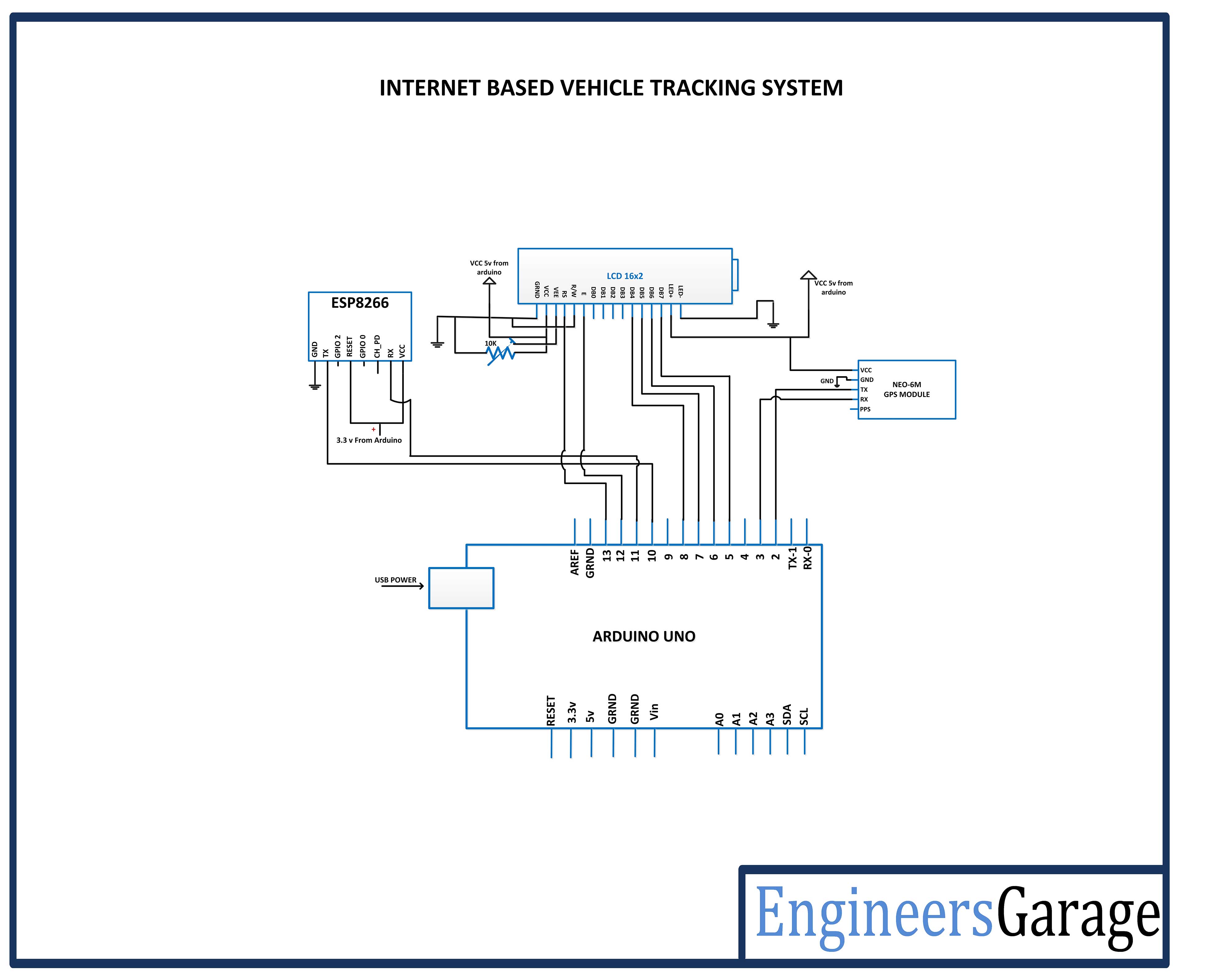 |