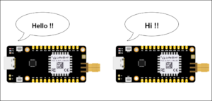
Communication between two LoRa end node devices can occur seamlessly. Both end node devices include the LoRa E5 Mini Board, which quickly switches between sending and receiving messages – making two-way communication possible.
In this configuration, communication begins with a device sending a message and waiting for confirmation. Upon receipt, the receiving device sends a response confirming that the message was received. This simple exchange shows how efficient and reliable LoRa technology is for communication.

Initial communication between LoRa E5 Mini Boards.
Abstract
- Identify the original ST-Link
- Upload the code for the Lora E5 Mini Board
- Learn to send and receive messages
- Learn how to program the flow or algorithm
Requirements
- Lora E5 mini card from Seed Studio
Loading the code
The code is carefully crafted so that the LoRa E5 Mini efficiently receives data through a universal asynchronous receiver transmitter (UART). It then sends this data to another node device.
For simplicity, a project file and corresponding hex file are included.
The hexadecimal file is uploaded directly to the LoRa E5 Mini Board, making the installation process more efficient. This approach ensures a user-friendly experience when using all the features of the LoRa E5 Mini.
However, the project file requires compilation in the STM32cube IDE before it can be loaded onto the E5 Mini Board.
Here are the steps…
1. Locating a genuine ST-Link V2 is important for LoRa code as ST-Link clone variants may not be compatible. This means that it is necessary to recognize the original ST-Link. A reliable method of identification involves examining the hardware components.
After thorough analysis, a genuine ST-Link V2 has an STM chip, indicating authenticity. Clones are typically imported from China and have a slightly different appearance.
This project requires a smooth “flashing process”, which occurs reliably with a genuine ST-Link with STM chip (see image below). Knowing the difference will ensure compatibility and proper programming.
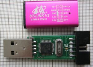
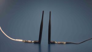
An original ST-Link V2.
2. Connect five wires to the LoRa E5 Mini Board as shown in the image below, including 3V3, SWDIO, SWCLK, RST and GND.
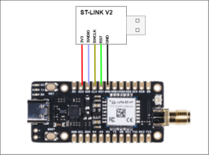
The ST-Link connection for LORAE5.
3. Open the STM32CUBE Programmer and click the 'Disconnect' button.
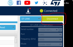
The 'Disconnect' target from the STM32CUBE programmer.
4. Select the hex file by clicking the Open File tab.
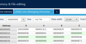
An open hexadecimal file.
5. Click on the 'Download' button to upload the code.
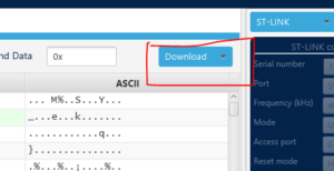
The code upload process.
6. Once a pop-up appears, the download process has completed and occurred correctly.
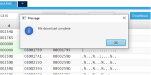
The download process is complete.
How to send and receive messages
Sending and receiving messages.
Connect the device to a computer and open the 'Serial Terminal'. The Arduino Serial Terminal is used as a demonstration below.
1. Connect the device to the respective port and open the Serial Terminal, Baud Rate 9600, and select 'NL' and 'CR' as shown in the image.
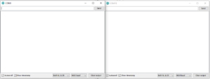
The serial terminals.
2. Send any message from one serial terminal and it should appear on the second terminal. If the sender receives the response, “ SENT CONFIRMED!! ”The message was received successfully.
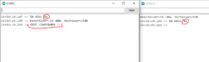
Communication between Serial Terminals.
The algorithm
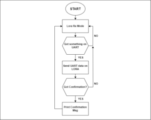
A block diagram of the complete algorithm.
Understanding the code
1. When the code starts, it 'starts listening on the UART' and 'starts receiving' on the Lora.
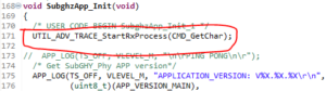
“Listen” on the UART.
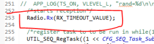
Lora RX began.
2. Below is the CMD_GetChar function, which will be called when there is data on the UART. When this occurs, the UART stores until '\n' is detected. It then sends the stored buffer to LoRa.
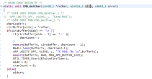
The UART function.
3. If there is no response from the receiving device, this function will be called…
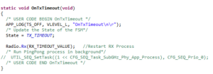
The timeout.
4. When the device receives data in LoRa, it prints the RSSI and SNR values.
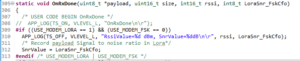
The printed RSSI and SNR values.
5. When the device receives data via LoRa, it compares the string. If the string is '*' then the message has been acknowledged. If there is some other string meaning, it will print the message in serial and send '*' to another device to confirm that the message was received.
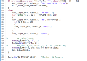
The message handling process in LoRa.
The messaging device
The messaging device example above can go from a simple idea to a real process with practical improvements. The integration of screen, keyboard and battery makes it significantly more portable and valuable, allowing for better user interaction.
Implementing a low-power sleep mode can extend the battery life of your device. This would be ideal in remote areas without reliable internet access. The device can ensure smooth data exchanges.
For greater security, messages can be transformed into secret codes, ensuring private communication. Using an encryption method keeps data secure and prevents unauthorized entry, making the device more secure.
These improvements allow the device to become a reliable tool for connecting in remote locations, providing a form of communication that would not otherwise exist.