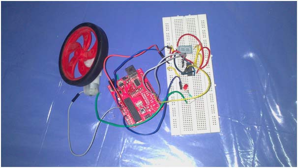
A tachometer is a device used to measure the rotational speed of any device. Using the analog voltage reading property of an Arduino, this can be easily implemented using the appropriate parts. Tachometers have a variety of applications, including measuring the speed of DC motors to ensure they are operating within specifications.
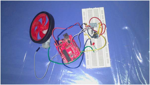
Fig. 1: Arduino-based digital tachometer prototype
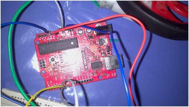
Fig. 2: Image of the Arduino microcontroller board
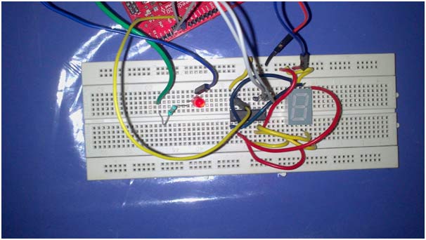
Fig. 3: Image of the tachometer circuit on the breadboard
Required components:
- Arduino board with ATmega32 microcontroller
- Any DC motor (preferably battery operated)
- Motorized wheel
- Resistor
- Potentiometer
- Seven-segment display
- Jumper Wires
- IC7447
- LED
Working principle.
· In order to make a tachometer , we will have to convert the rotational speed into a readable format. The only way the Arduino can read it is in terms of electrical voltage.
· It is well known that if voltage is supplied to a motor, the wheel of the motor will rotate, the speed of which is determined by the amount of voltage supplied. However, the reverse is also true, which means that if we run the motor alone, we can get a voltage at both ends of the motor terminals.
This voltage can be fed to the Arduino and the Arduino can calculate the rotation speed depending on how much voltage was fed to the rotating motor.
Procedure and Guidelines
Procedure and Guidelines
- The circuit diagram is shown in the circuit diagram tabs. Circuit Diagram 1 – circuit diagram without using driver IC and Circuit Diagram 2 – circuit diagram using 7-segment display driver IC7447.
- The motor is connected to a resistor and an LED diode. The resistor is used to prevent excess current that would normally damage the Arduino. The LED is used to indicate when the engine is running and also to prevent reverse operation.
- Since we have so many pins left from the Arduino, we can connect them directly to the 7-segment display. Alternatively, we could use a seven-segment display driver, which would reduce the number of pins used and also make the implementation easier in terms of the coding process.
- Once the motor is turned on, a positive voltage will be supplied to the arduino analog pin.
- The Arduino will process the analog reading. As we use a seven segment display, we can have 10 values i.e. from 0 to 9. We can program the arduino to divide the obtained analog reading into 9 divisions which will give the required output from 0 to 9 in the seven segment display.
- If the IC7447 is used, one more step is added in which the values 1 to 9 are converted to their binary equivalents before being passed on to the appropriate pins of the IC.
- In case a perf board is being used, you must be careful not to solder the IC itself, instead an IC bracket
- As a precaution, always test the motor voltage first. This can be done by connecting a multimeter to the two terminals of the motor and turning the motor manually by hand. If the voltage reading is more than 12V, the motor should not be used as there is a chance of damaging the Arduino board.
- If you want to adjust the sensitivity of the instrument, you can use a potentiometer instead of the resistor. The lower the resistance, the greater the sensitivity.
Project source code
###
intval=0; intbinVal; void setup { Serial.begin(9600); //serial setup pinMode(3,OUTPUT); pinMode(4,OUTPUT); pinMode(5,OUTPUT); pinMode(6,OUTPUT); pinMode(A2,INPUT); } void loop { val = analogRead(A2); // read the input pin Serial.println(val); // debug value binVal=val/1024*9; switch(binVal){ case 0: digitalWrite(3,LOW); digitalWrite(4,LOW); digitalWrite(5,LOW); digitalWrite(6,LOW); break; case 1: digitalWrite(3,HIGH); digitalWrite(4,LOW); digitalWrite(5,LOW); digitalWrite(6,LOW); break; case 2: digitalWrite(3,LOW); digitalWrite(4,HIGH); digitalWrite(5,LOW); digitalWrite(6,LOW); break; case 3: digitalWrite(3,HIGH); digitalWrite(4,HIGH); digitalWrite(5,LOW); digitalWrite(6,LOW); break; case 4: digitalWrite(3,LOW); digitalWrite(4,LOW); digitalWrite(5,HIGH); digitalWrite(6,LOW); break; case 5: digitalWrite(3,HIGH); digitalWrite(4,LOW); digitalWrite(5,HIGH); digitalWrite(6,LOW); break; case 6: digitalWrite(3,LOW); digitalWrite(4,HIGH); digitalWrite(5,HIGH); digitalWrite(6,LOW); break; case 7: digitalWrite(3,HIGH); digitalWrite(4,HIGH); digitalWrite(5,HIGH); digitalWrite(6,LOW); break; case 8: digitalWrite(3,LOW); digitalWrite(4,LOW); digitalWrite(5,LOW); digitalWrite(6,HIGH); break; case 9: digitalWrite(3,HIGH); digitalWrite(4,LOW); digitalWrite(5,LOW); digitalWrite(6,HIGH); break; default: break; } }###
Circuit diagrams
| Arduino Based Digital Tachometer Circuit Diagram | 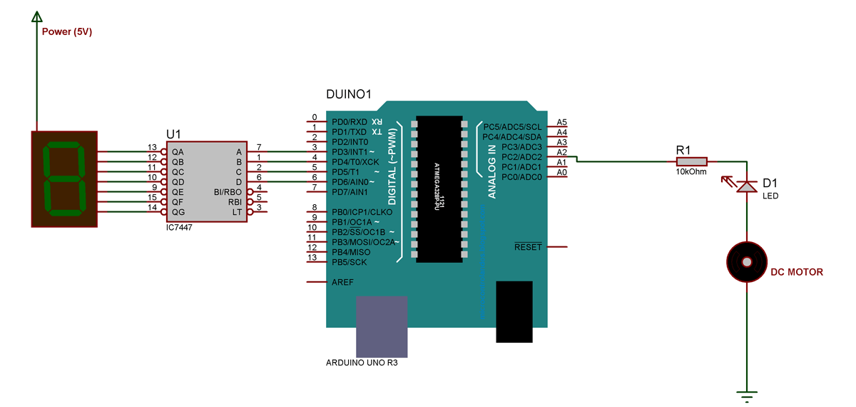 |
| Circuit Diagram-Digital Tachometer Based on Arduino_0 | 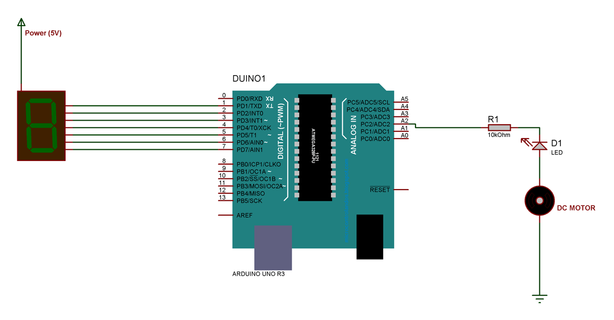 |

