RFID is a popular tagging and identification technology. Radio frequency identification involves an RFID tag and second RFID reader. RFID tags and tags are low cost and easily available. Compared to barcode tracking systems, RFID solutions have several advantages. One of the apparent advantages of RFID over barcodes is that it does not require line of sight to read. RFID readers capture the information encoded on RFID tags using radio frequency signals. RFID is a perfect contactless identification and tagging technology that is easy to implement and use. This is why RFID is the preferred choice for various applications such as access control systems, automatic toll collection, contactless payment, automated check-out systems and inventory tracking.

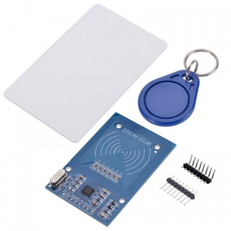
Example of MFRC522 RC522 RFID module.
There are several RFID readers available. One of the popular RFID readers is the MFRC522 from NXP. This RFID reader can be connected to a controller/computer using UART, SPI and I2C protocols. The RFID reader/writer IC in the MFRC522 uses a radio frequency of 13.56 MHz for its operation. MFRC522 RC522 can read/write RFID cards and tags built using the ISO/IEC 14443 protocol. This includes MIFARE compatible RFID tags such as MIFARE-mini, MIFARE-1K, MIFARE-4K RFID tags, key fob and NTAG RFID cards.
This project interfaces the MFRC522 RC522 RFID reader with Arduino and reads NUIDs from MIFARE compatible cards and key fobs. We also demonstrated a simple access control system using the RFID reader and RFID tags using Arduino.
Required components
- Arduino UNO/Arduino Mega x1
- RFID reader MFRC522 RC522 x1
- RFID Cards and Key Fobs MIFARE Classic-1K x Minimum 2
- Connecting wires/jumper wires
MFRC522 RC522 RFID Reader
An RFID solution uses radio frequency electromagnetic waves for data communication. The system consists of two components – one is an RFID transceiver and the second is an RFID transponder. The RFID transceiver reads/writes data encoded on RFID transponders via a low-frequency radio signal. Transponders are RFID cards, key fobs, tags or stickers with an integrated EEPROM that stores encoded data.
Each RFID transponder has an identification number which can be a 7-byte Unique Identity Number (UID) or a 4-byte Non-Unique Identity Number (NUID). The main component of an RFID card/tag/sticker is an RFID chip. RFID chips can be read-only or programmable. The UID or NUID of a read-only card cannot be changed or modified, including other data stored on the chip. Programmable chips usually come with a pre-programmed chip identification code that can be replaced with additional memory using an RFID transceiver.
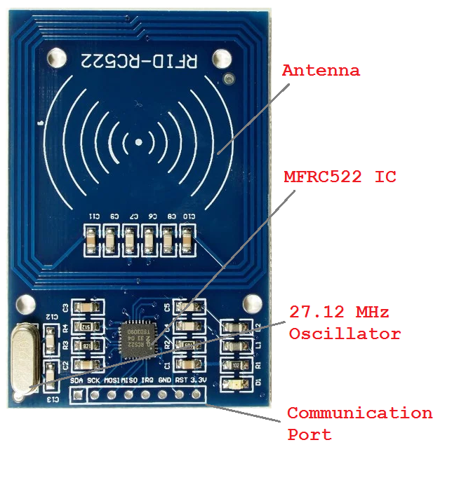
MFRC522 RC522 RFID reader components.
NXP's RC522 RFID reader is designed to read/write RFID transponders based on the ISO/IEC 14443 protocol, including MIFARE and NTAG RFID cards/tags/stickers. The reader is referred to as the Proximity Coupling Device (PCD), and the labels/stickers/cards are referred to as the Proximity Integrated Circuit Board (PICD). The reader can communicate with a controller/computer using SPI, I2C and UART protocols. It reads/writes tags at a frequency of 13.56 MHz with an operating range of 50 mm. The RC522 reader has an MFRC522 chip, a 27.12 MHz oscillator, RF antenna and other integrated components. The operating voltage of the reader is 2.5~3.3V. However, the communication port of the reader is tolerable at 5V. Therefore, it can be directly interfaced with 5V microcontrollers like Arduino.
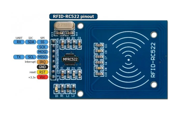
MFRC522 RC522 RFID reader pin configuration.
The reader has the following pin configuration.
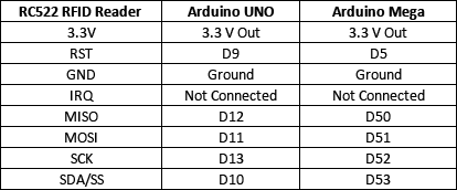
Circuit Connections
The RC522 RFID reader supports SPI, I2C and UART protocols for communicating with a controller/computer. For Arduino, we have a library that only supports the SPI protocol. Furthermore, SPI is the fastest among all three serial communication protocols. This is why we are interconnecting the RC522 reader with the Arduino using a physical SPI port. To interface RC522 with Arduino via SPI, follow the circuit connections mentioned in the table below.
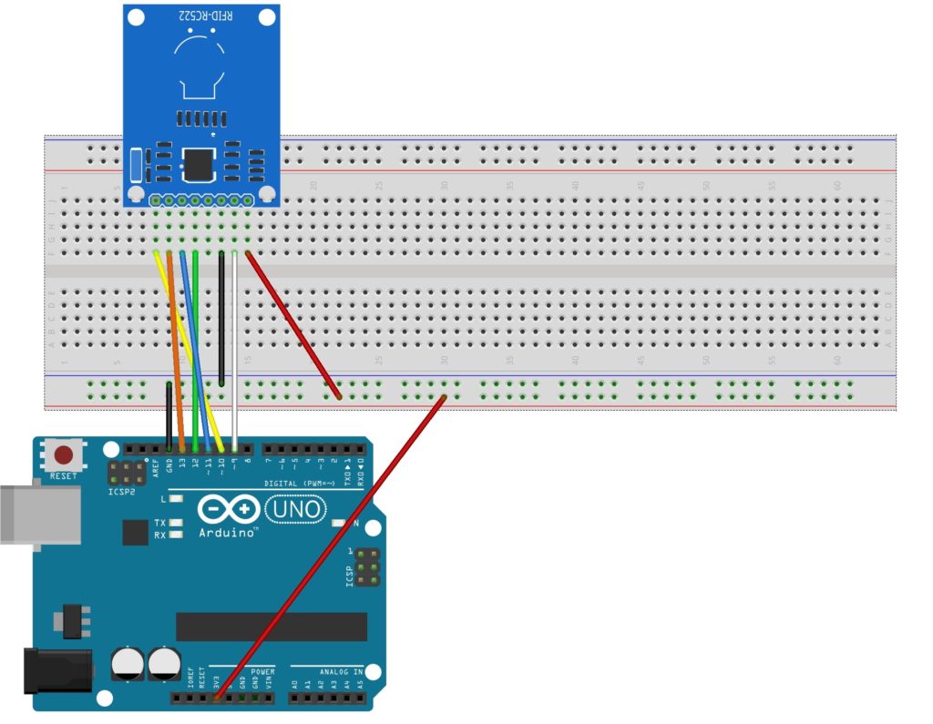
Circuit diagram for interfacing MFRC522 RC522 RFID reader with Arduino
Arduino library for RC522 RFID reader
Circuit connections can be made after placing the module on a breadboard. Connections follow the circuit diagram below.
Currently, there are several Arduino libraries available for RC522. The library used in this project is the Arduino MFRC522 Library by miguelbalboa, available on Github. Download the library as a ZIP file. Navigate to Sketch->Add Library->Add .ZIP Library in Arduino IDE. Select rfid-master.ZIP and the library for RC522 will be added to the Arduino environment.
Dumping data from RFID tags to Serial Monitor
The Arduino library for RC522 itself comes with many examples. One of the useful examples is DumpInfo. This example reads all the data on the RFID transponder chip and prints it to the Serial Monitor. Navigate to Files->Examples->MFRC522->DumpInfo.
Load the sketch into Arduino and run Serial Monitor. When reading a MIFARE Classic-1K RFID tag, the Serial Monitor output is as follows.
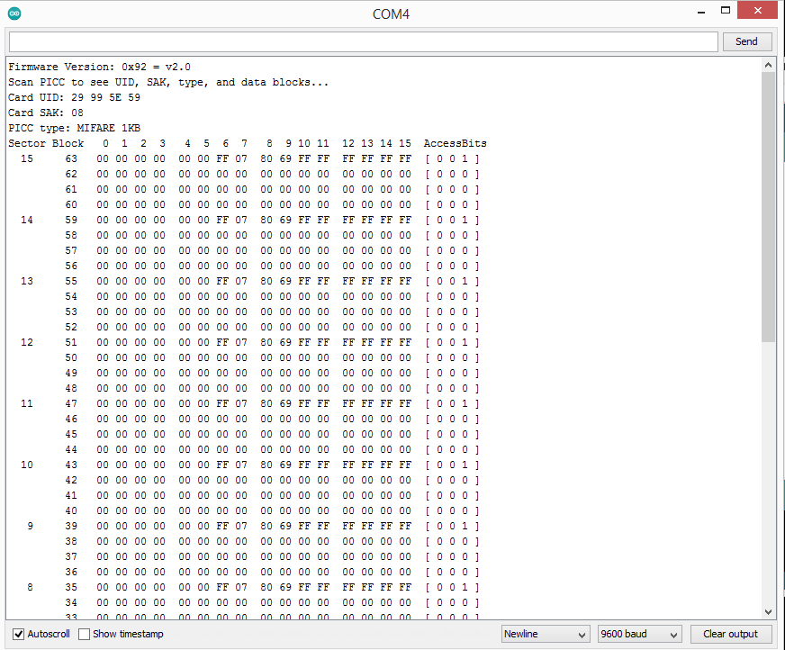
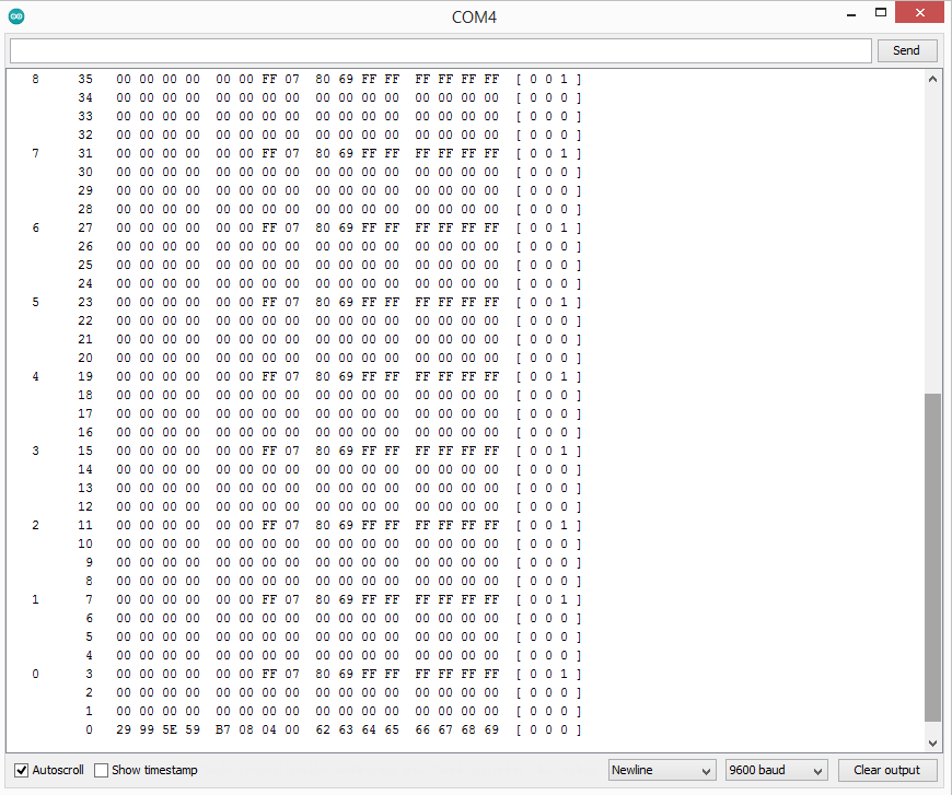 MIFARE Classic-1K RFID Card Memory Map
The images above are screenshots of reading a MIFARE Classic-1K RFID card. As can be seen in the images above, the RC522 read all the data stored in the RFID card's on-chip memory. The on-chip memory is divided into 16 sectors, where each sector consists of 4 blocks. Each block stores 16 bytes. In each sector, the first three blocks are data blocks and the fourth block is the final block that contains two secret keys and access bits. The access bits determine the read/write or read-only status of the sector. The first block contains manufacturer information in the first sector, i.e. sector 0, and a trailer block only follows two data blocks.
Arduino Sketch
How the project works
In this project, we read the NUIDs from RFID cards/key fogs and display the read NUID in Serial Monitor in decimal and hexadecimal format. The NUID is 4 bytes long and identifies a specific RFID tag/label/card/sticker.
Upload the above sketch to Arduino UNO/Arduino MEGA after making proper circuit connections. Open Serial Monitor and set the baud rate to 9600. When contacting a tag/card/key, the NUID of the respective tag/card/key is read and displayed in Serial Monitor in decimal and hexadecimal formats. Sketch also compares tags/keys to a given NUID to demonstrate access control using RFID cards/keys.
The code
The outline begins with importing SPI and MFRC522 libraries to work with RC522 RFID readers via the SPI protocol. The pin assignments for SDA and Reset are defined and an MFRC522 object is instantiated with these pins. A variable to store the MIFARE key is defined. A byte array 'nuidPICC ' is defined to store 4 bytes of RFID NUID. Variables are declared to store string representations of the NUID in decimal and hexadecimal formats. Similarly, a variable is defined to store a string representation of the MIFARE key.
In the setup function, the baud rate for serial communication with Serial Monitor is set to 9600 bps using the Serial.begin method. The SPI protocol is initialized using the SPI.begin method. The RFID module initializes the PCD_Init method on the RFID object. The bytes of the MIFARE key are set to FF and stored in an uppercase string representation. The MIFARE key is published in Serial Monitor.
In the loop function, the RFID card/key/tag is detected by calling the PICC_IsNewCardPresent method on the RFID object. Next, the card's NUID/UID is read by calling the PICC_ReadCardSerial method on the RFID object. The MIFARE card type is detected using the PICC_GetType(rfid.uid.sak) method and displayed in Serial Monitor. Then the individual bytes of the NUID are accessed using the rfid.uid.uidByte property. First, the bytes are serialized in decimal format and converted to a string object. The string containing a decimal representation of the NUID is published to Serial Monitor. Then the bytes are serialized in hexadecimal format and converted into a string object. The string containing a hexadecimal representation of the NUID is published to Serial Monitor. The bytes read from the NUID are stored in a character array. This character array is compared to a predefined NUID using the user-defined compareNUID function. The function returns a Boolean value used to determine access control. The reader is prevented from reading the card by calling the PICC_HaltA method on the RFID object. Finally, encryption is stopped by calling the PCD_StopCrypto1 method on the RFID object.
Results
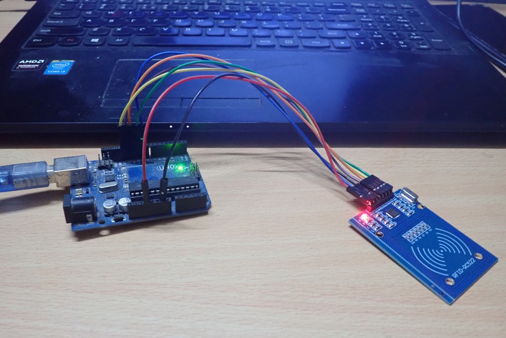
Circuit for interfacing MFRC522 RC522 RFID reader with Arduino
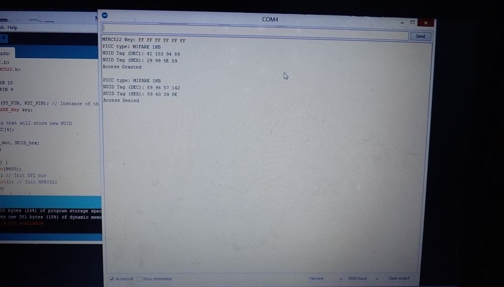
Arduino Serial Monitor showing NUID of RFID tags using RC522 module
Demo video