One can use a cell phone with any cellular network around the world if the proper SIM card is inserted in it. This is possible because there is a device inside the cell phone that follows a global standard that allows connection to different cellular networks. This standard is called Global System for Mobile Communications (GSM). Cell phones have built-in GSM modules that can be used by the phone's internal processor to make a call, send or receive messages or even connect to the GPRS network.
In certain applications, microcontroller-based systems must be connected to the GSM network, which will allow the user to control the system by sending messages or making a call. Systems can also send messages to the user to alert or inform them of the status of the running system. In all these cases, a separate GSM module is used instead of using cell phones. There are GSM modules available that can do serial communication with microcontroller-based systems. Communication is done by sending or receiving AT Commands .
This specific project demonstrates how to interface a GSM module with Arduino and have them call a specific cell phone number. The GSM module in this project interfaces with the Arduino easy prototyping platform, which makes the hardware circuit simple and easy to write code using the C-based programming environment.
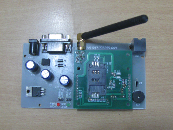
The GSM module used in this project is a SIM900 based module that can communicate with other devices using the RS232 serial communication port. It works with a 9V power supply and its image is shown below:

Fig. 2: GSM SIM900 module connected to the Tx pin of the Arduino board module through max232
Arduino is an open source hardware where the hardware schematic is open, anyone can use this schematic to develop their Arduino board and distribute it. The Arduino IDE is also open source and anyone can contribute their libraries to Arduino. All Arduino boards must be compatible with the Arduino IDE, which can be used to program Arduino boards.
The Arduino board used in this project is the Arduino pro-mini board and the IDE version of Arduino is 1.0.3 for Windows. The image of the Arduino pro-mini board and Arduino IDE is shown below:
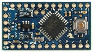
Fig. 3: Typical Arduino Pro-Mini board
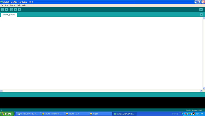
Fig. 4: Arduino IDE software window
Since the Arduino pro-mini board does not have circuitry to interface with the PC's serial port or USB port, an external USB to TTL converter board is required to connect it to the PC. This hardware helps in programming the Arduino board and also helps in serial communication with the USB port of the PC.
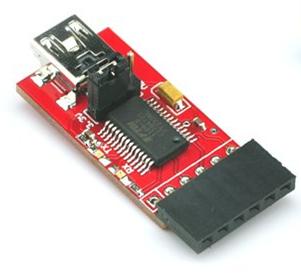
5: External USB to TTL Converter Board for Arduino Programming and Serial Communication
It is assumed that the reader has gone through the blueprint for how to get started with Arduino and tried out all the things discussed there.
The Arduino board can act as a standalone system with the ability to receive inputs, process the input and then generate a corresponding output. It is through these inputs and outputs that Arduino as a system can communicate with the environment. Arduino boards communicate with other devices using standard digital input/output communication ports such as USART, IIC and USB, etc.
In this particular project, the GSM module is connected to the Arduino board using the serial communication port. Since the module has an RS232 port and the Arduino pro-mini can communicate using TTL logic levels, a max232 IC is used to do a bidirectional conversion between RS232 and TTL logic levels. The Tx pin of the Arduino board is connected to the Rx pin of the GSM module through max232 and the Rx pin of the Arduino is connected to the Tx pin of the GSM module using the max232 itself.
The code written on Arduino is capable of communicating with the GSM module using AT Commands . AT Commands are sent or received from the module using the serial communication functions provided by the Arduino library. The functions like Serial.begin which helps to initialize the serial port with a certain baud rate, Serial.write to send data to the serial port, Serial.available and Serial.read functions to read data from the serial port are used in this project and have already been discussed in previous projects about how to do serial communication with Arduino, how to send and receive serial data using Arduino and how to do serial debugging with Arduino.
GSM modules respond “OK” when they receive the “AT” command and it is the best way to check communication between the module and the microcontroller. The command to make a call to a number is “ATD”;
SYNTAX: ATD
For example,
ATD123456789;
Try sending the command from the PC with the help of some serial monitoring software and make sure that the module is making a call to the specified number. Then you can check and upload the code that can send the same commands to the Arduino board as explained in the project how to start using Arduino. Once the board reboots after successfully uploading the code, the Arduino sends the same command to the GSM module allowing it to make a voice call to the number specified in the code.
Make sure that the GSM module has been turned on at least 2 minutes before the Arduino board starts sending commands for the GSM to establish communication with the cellular network corresponding to the SIM card inserted into it.
Project source code
### /*============================= EG LABS ================== =================// Demonstration on how to interface GSM module and make a call The circuit: LCD: * LCD RS pin to digital pin 12 * LCD Enable pin to digital pin 11 * LCD D4 pin to digital pin 7 * LCD D5 pin to digital pin 6 * LCD D6 pin to digital pin 5 * LCD D7 pin to digital pin 4 * LCD R/W pin to ground * 10K resistor: * ends to +5V and ground *wiper to LCD pin 3 * LED anode attached to digital output 9 * LED cathode attached to ground through a 1K resistor GSM: RX PIN OF GSM TO TX0 PIN OF ARDUINO SHORT THE GROUND PINS OF ARDUINO AND GSM =============================== EG LABS ================== =================*/ #include// initialize the library with the numbers of the interface pins LiquidCrystal LCD(12, 11, 7, 6, 5, 4); // give the pin a name: int led = 9; void setup { pinMode(9, OUTPUT); lcd.begin(16, 2); lcd.print("ENGINEERS GARAGE"); lcd.setCursor(0, 1); lcd.print(" GSM CALLING "); // initialize the led pin as an output. pinMode(led, OUTPUT); // start serial port at 9600 bps Serial.begin(9600); // wait for a while until the serial port is ready delay(100); Serial.print("ATD09895941988;nr"); } void loop { digitalWrite(led, HIGH); delay(1000); digitalWrite(led, LOW); delay(1000); } ###
Circuit diagrams
| Circuit diagram for making phone calls using Arduino | 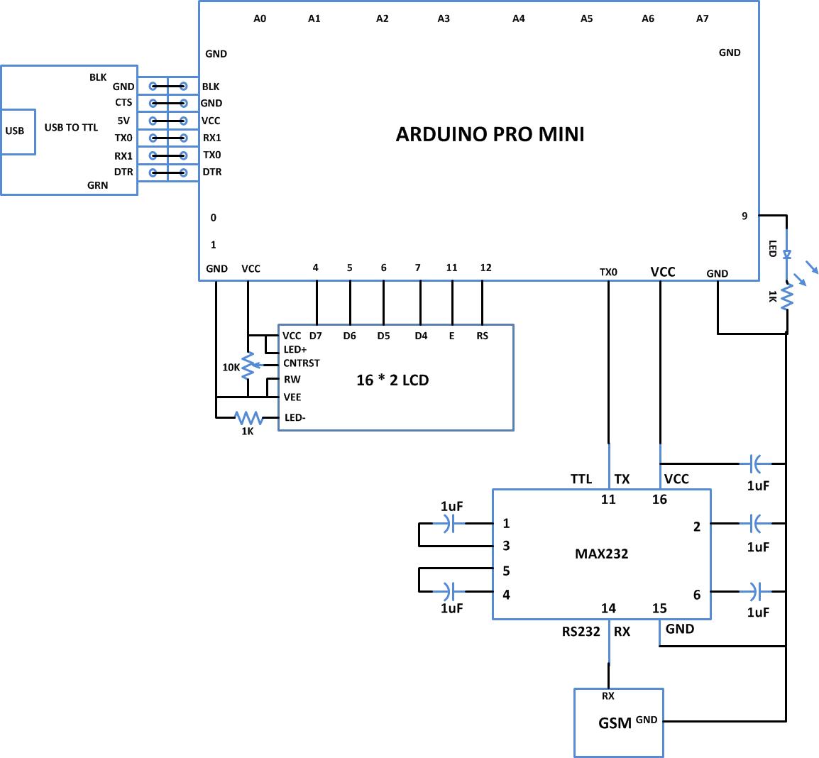 |
Project Components
- Arduino ProMini
- Capacitor
- LCD
- LED
- MAX232
- Potentiometer
- Resistor