Drawing or painting a picture is a great technique for expressing your thoughts. In the broad concept of industrial design, technical drawing is an essential skill for designers who work with the production of real objects.
Technical drawings use standardized language and symbols to accurately and visually represent all the information needed to produce a product or part.
This guide is designed to help you develop a clear understanding of technical drawings that accurately communicate your design intent to your suppliers.
How to use a technical drawing for technical verification? Here is a practical application.
Go now!

What is a technical drawing?
Engineering drawings, also known as mechanical drawings, manufacturing plans, drawings, etc., are technical drawings that show the shape, structure, dimensions, tolerances, accuracy and other requirements of a part in the form of a plan. They help define the requirements of a structural part and convey the design concept.
Engineers use technical drawings to convey information about a specific object. The term “detail drawing” refers to a drawing commonly used to indicate the geometry needed to construct a component. Even the simplest components require many drawings to fully describe them.
A technical drawing can be used as a starting point for creating shop drawings, manufacturing plans, technical drawings, more comprehensive dimensional drawings, etc. Detailed information about the drawing, e.g. Information such as who designed it and who approved it is contained in a title block or information field.
Why use technical drawings?
The technical drawing of a single part visually represents the structure, dimensions, tolerances and other requirements of a part. In the manufacturing industry, a single-piece drawing is often used as a processing unit.
An assembly drawing allows an engineer to represent a machine/equipment that is assembled from multiple parts to achieve a specific function. Assembly drawings are often used to verify that the actual manufacturing of individual parts meets assembly requirements.
How to create a technical drawing

There are two common methods for technical drawings: manual drawing and computer drawing.
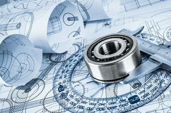
Drawing boards, paper, rulers, calipers, and rulers are essential tools for drawing by hand. They are suitable for university courses and play an important role in developing spatial imagination and conceptual skills that support creative thinking in university students.
Computer drawings, commonly used in CAD software, are more suitable for modern manufacturing industries. CNC machining centers equipped with CNC systems can read data and information directly from digital files and create corresponding machining programs, saving time and effort. At the same time, computer-aided drafting makes it easier to modify drawings, allowing you to maintain different versions of the design and eliminating the laborious process of manual drafting.
The 3D model can also be used in machining centers, but it requires technical drawings to convey important information such as materials, tolerances, special requirements, etc. We generally recommend using a 3D model in conjunction with technical drawings.
Basic components of a technical drawing
title block

The title of the technical drawing block document is located in the lower right corner of the page. Also called an information block, it contains the name of the part, the names of the people who worked on the part (design, review and approval), the company name, the drawing number and other relevant information.
Furthermore, it includes technical details such as measurement units, projection angles, surface polishing criteria, scale and construction material. Title blocks are used to better understand all parts of the technical drawing.
coordinates

In large or complicated technical drawings, coordinates are often used and positioned along the boundaries of the drawing. When discussing the content of the drawing, these reference points serve as a guide.
Types of lines
A technical drawing does not have uniform lines. The visible and hidden boundaries, centerlines, and other details of a part can be displayed using various selections. Below are the line types.
Continuous line
A line drawing or a continuous line is the most common method. Visually represents the physical boundaries of an object. In other words, a continuous line is used to draw real objects. Line thickness is varied; Thicker lines are used for the outer contour and thinner lines for the inner contour.
Hidden lines

Lines that are not visible to the naked eye can reveal information that would otherwise be obscured by drawings. The length of an internal step in a rotated part can be displayed using hidden lines instead of a section or clipping view.
Center lines
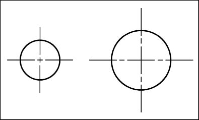
Parts with symmetrical holes and features can be represented using centerlines. Symmetry can reduce the number of dimensions in a drawing and make it more visually appealing, making it easier for the reader to understand.
Dimension lines

The recorded data is described using auxiliary lines. Two arrowheads separate the guidelines on the dimension line from the measurement taken above (or internally, as in the image above).
Broken preview lines

When a view is broken, break lines appear. For a part 3,000 mm long and 10 mm wide and with the same geometric properties, a breakout provides all the information without taking up much space.
CNC machines require full views of parts in order to cut them. Alternatively, the production engineer must recreate the entire part based on measurements alone.
Cutting Flat Lines
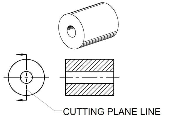
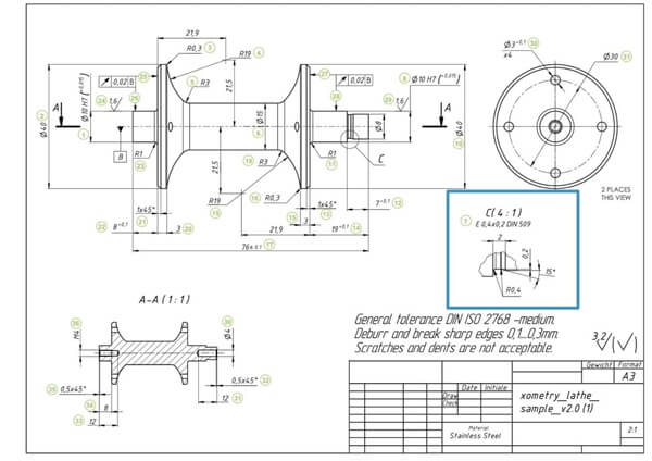
Section plane lines illustrate the section path in a section view. Section line AA can be seen here and shows both types of holes.
Dimensions and measurements
A dimension is a numerical value that expresses the size, position, orientation, shape, or other geometric properties of a part in appropriate units of measurement. Dimensioning is, therefore, the process of representing the size of an object, as well as all other important data for its construction and function, in a drawing through lines, numbers, symbols, annotations, etc.
The shape and size of an object must be known before it can be constructed. Therefore, a technical drawing is required that shows the shape, dimensions and other relevant data of the object. The size and location of various features of the object are indicated by specifying dimensions. For example, it is used to determine the dimensions of the object, the name of its parts, and the diameter of the hole.
Furthermore, when machining parts, it is often difficult to ensure that a length of 10mm is 100% 10mm and the final product can be 9.9mm or 10.2mm long. This can be achieved by defining tolerances to limit upward and downward deviations and help suppliers understand important dimensions.
Types of visualizations
Used to express the external structure of the part shape. There are basic and auxiliary views, the latter including an oriented view, a partial view, and an oblique view.
Orthographic view
The orthographic view is the core of the content of a technical drawing. A 2D representation of a three-dimensional object is called an orthographic view or orthographic projection.
A 2D view must therefore provide all the information necessary to produce a part. Length distortions are avoided with this representation.
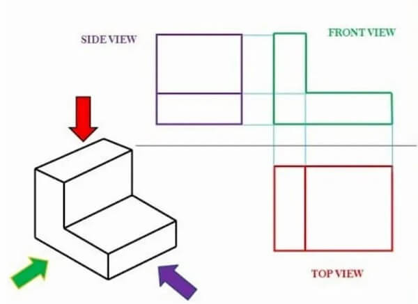
Multiview drawings are the most common method of conveying all necessary information and generally contain three views:
It is conceivable that some additional views are needed to display all the information. Less is definitely more.
Opinions vary somewhat regionally. Compare the US and ISO layouts by looking at this image.

The drawing layouts in ISO and in the United States are in direct conflict with each other.
The left projection is called the first angle projection. In this arrangement there is a top view, a front view, a side view, etc. In Europe, the ISO standard is the most commonly used.
To the right of the image you can see a projection from a third angle. All these images are organized in chronological order. This arrangement is particularly popular in the United States and Canada.
Isometric view

The image above is an example of an isometric view. Isometric drawings represent three-dimensional objects. Compared to the front view, all vertical lines remain vertical and parallel lines are represented at an angle of 30 degrees.
Vertical and parallel lines are the correct length. For example, you can easily measure the length of a paper drawing by using a ruler and scaling the image. This is not the case with slanted lines.
It is important to know the difference between an isometric view and a perspective view. In art, perspective views represent an object as it appears to the human eye. Engineers don't rely on optical illusions, they stick to facts.
Partial view

A partial view is a view obtained by projecting part of an object onto the base projection plane. Use arrows with letters to indicate the part to be displayed, the projection direction and indicate the name of the view. The local view can be configured in the form of the base view or configured and marked in the form of the view direction configuration.
Detailed view
A detailed view shows the model in its entirety, as a label or segment in other views. The detailed view typically displays the model at a much finer level of detail than the main view.
Auxiliary view
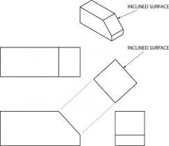
An auxiliary view is an orthographic view for non-horizontal or non-vertical planes. Helps in distortion-free representation of inclined surfaces.
Oblique view

An oblique view is a view of an object projected onto a plane that is not parallel to the base projection plane. The oblique view is usually configured in the form of a directional view, where an arrow with a capital letter indicates the direction of projection and the same letter is marked above the corresponding oblique view. If necessary, a rotated configuration of the oblique view is permitted. The capital letter indicating the name of this view must be close to the end of the arrow of the rotation symbol, and it is also allowed to indicate the rotation angle after the letter.
In real production, the shape of the part is very different. The above views alone are not sufficient to clearly express the internal and external shape and structure of the piece. For this reason, there are several ways to express the shape and structure of the part: sectional view, cross-sectional view, enlarged partial view, etc.
cut
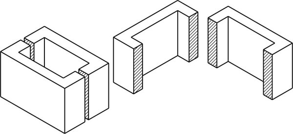
You can better represent the inside of a complicated object, such as a car engine block, by sketching the object as it would look if it were cut out. This will erase the many hidden lines in the sketch.
Sectioning is the process of drawing the internal structure of an object, representing it as if it were cut. Sectioning is a common feature of many industrial designs.
If you divide the above block, you will get blocks A and B as shown. An object in a painting or sketch can be divided into any shape, such as an apple.
Complete sectioning

This type of cutting is called full cutting when the line of a cutting plane passes completely through an object.
Cutting an object can be done whenever a closer look is needed. As you can see, this object has been cut in half.
Half section view
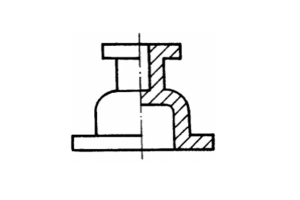
If the part has a symmetrical plane, the graphic projected onto the projection plane perpendicular to the symmetrical plane may be bounded by the symmetrical centerline, half of which is drawn as a sectional view and the other half as an elevation. This sectional view is called a half-section view. The half-section view is used for symmetrical elements whose internal and external structures need to be expressed. The dividing line of the half-section view is drawn with a single dotted line. Due to the symmetry of the graph, the internal structure of the parts was clearly expressed in the section and no hidden lines were drawn on the visualized part.
Broken Sections

Cropped views can be used to reveal the internal details of the model by cutting the material to a specified depth. The broken part is defined by a closed profile, usually a spline. Users can enter an exact depth or reference a location in another view to specify a depth.
Cross-sectional views
With respect to the cross-sectional area of an object, the orthographic projection of that object's cross-section is equal to its total area. For example, a cylinder of height h and radius r, when viewed in the orthogonal direction and along its central axis, has
Partial enlargement
Using partial views in technical drawing documentation makes it easier to provide the necessary details about parts. It is often easier to see more details about a part if you use partial views of the part.
Assembly drawings
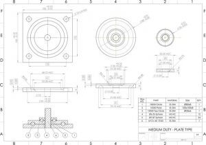
Engineers often make the mistake of trying to contain all the information about each individual part in an assembly drawing. This can be avoided if you remember that the objective of these technical drawings is to facilitate the assembly process.
To achieve this, you can use tools such as section views, numbered parts, general dimensions, cross sections, and detailed (or close-up) views.
Regardless of the fixing method, it must be clear where each component belongs and how it is fixed. To your advantage, make sure the bill of materials contains accurate information about part numbers, names, and quantities. All of this helps you create assembly drawings that make your machine shop projects more efficient.
4 common mistakes in technical drawing
1. Dimensions marked as incomplete, chaotic, omitted or repeated.
(1) The essential dimensions of the parts must be immediately marked.
(2) Avoid the appearance of closed dimensions.
(3) Mark the size for easy processing and measurement.
2. View the error. Visualizations are poorly positioned or mismatched and do not clearly express design intent.
3. The requirements for the dimensional accuracy of the part are high, but the dimensional tolerances are unclear, resulting in large machining errors and scrap parts.
4. The technical requirements of parts (including dimensional tolerances, shape tolerances and surface roughness) are not standardized.
Concluding
For designers, engineers and machinists, technical drawings are one of the best ways to communicate ideas and perspectives.
Designers and engineers clearly record part characteristics and communicate important information through drawings to help suppliers accurately capture important information, understand design intent, and develop machining solutions.