1. What is curvature tolerance?
Bending margin is statistical data accumulated by experienced mold designers over the years.
Later, mold designers can use this data in the calculation formula to determine the flattening size of various metal sheets.
Consequently, the bend allowance is a tool for mold designers to calculate the unfolding dimensions of press-bent parts.
The functions of bend tolerance:
Perforated mold designers know that the first step in the design process is to reverse the folded structure into a flat structure step by step after receiving the product drawings from the customer.
They then drill the flat structure and design the bending mold to meet the customer's needs.
The mold structure design must not only meet the customer's drawing requirements, but also the drawing's dimension tolerance requirements for accuracy.
The biggest challenge lies in ensuring the accuracy of the relevant stamping and bending unfolding dimensions.
2. How to calculate the bending margin?
After learning about bend tolerance, the next step is to calculate it.
You can directly use our bending tolerance calculator to calculate the bending tolerance.
In addition, the manufacturing calculator can also help you calculate K factor, Y factor, bending allowance, bending deduction, etc.
In a post on our blog we do a very detailed analysis of this, so go ahead and check out the method for calculating bend tolerance.
3. Bend tolerance chart
(1) Bending tolerance table for 88° and 90° bends
| Material | Thickness | Deduction |
Inside R |
Angle | To die | Punch | ||
|---|---|---|---|---|---|---|---|---|
| R |
V Width |
R | Angle | |||||
| Steel sheet | 0.8 | 1.5 | 1.3 | 90° | 0.5 | 8 | 0.2 | 88° |
| 0.9 | 1.7 | 1.3 | 90° | 0.5 | 6 | 0.2 | 88° | |
| 1 | 1.8 | 1.3 | 90° | 0.5 | 8 | 0.2 | 88° | |
| 1.2 | 1.91 | 1 | 90° | 0.4 | 6 | 0.2 | 88° | |
| 1.2 | 2.1 | 1.3 | 90° | 0.5 | 8 | 0.2 | 88° | |
| 1.5 | 2.5 | 1.3 | 90° | 0.5 | 8 | 0.2 | 88° | |
| Cold rolled Plate |
1.6 | 2.65 | 1.3 | 90° | 0.5 | 8 | 0.6 | 88° |
| 1.8 | 3.4 | two | 90° | 0.8 | 12 | 0.6 | 88° | |
| two | 3.5 | two | 90° | 0.8 | 12 | 0.6 | 88° | |
| 2.3 | 3.75 | two | 90° | 0.8 | 12 | 0.6 | 88° | |
| 2.5 | 4.2 | 2.6 | 90° | 0.8 | 16 | 0.6 | 88° | |
| 3 | 5.05 | 2.6 | 90° | 0.8 | 16 | 0.6 | 88° | |
| 4 | 6.9 | 4 | 90° | 0.8 | 25 | 0.6 | 88° | |
| Hot rolled Plate |
2.3 | 3.77 | 2.6 | 90° | 0.8 | 16 | 0.6 | 88° |
| 3.2 | 5.2 | 2.6 | 90° | 0.8 | 16 | 0.6 | 88° | |
| 4.2 | 7.4 | 4 | 90° | 0.8 | 25 | 0.6 | 88° | |
| 4.8 | 8.1 | 4 | 90° | 0.8 | 25 | 0.6 | 88° | |
| aluminum plate | 0.8 | 1.5 | 1.3 | 90° | 0.5 | 6 | 0.2 | 88° |
| 1 | 1.6 | 1.3 | 90° | 0.5 | 8 | 0.2 | 88° | |
| 1.2 | 2.1 | 1.3 | 90° | 0.5 | 8 | 0.2 | 88° | |
| 1.5 | 2.45 | 1.3 | 90° | 0.5 | 8 | 0.2 | 88° | |
| 1.6 | 2.7 | 1.3 | 90° | 0.5 | 8 | 0.6 | 88° | |
| 1.6 | 2.4 | 1.3 | 90° | 0.6 | 10 | 0.6 | 88° | |
| two | 3.25 | two | 90° | 0.8 | 12 | 0.6 | 88° | |
| 2.3 | 3.6 | 2.6 | 90° | 0.8 | 16 | 0.6 | 88° | |
| 2.5 | 4.2 | 2.6 | 90° | 0.5 | 16 | 0.6 | 88° | |
| 3 | 4.7 | 2.6 | 90° | 0.8 | 16 | 0.6 | 88° | |
| 3.2 | 5 | 2.6 | 90° | 0.8 | 16 | 0.6 | 88° | |
| 3.5 | 5.9 | 4 | 90° | 0.8 | 25 | 1.5 | 88° | |
| 4 | 6.8 | 4 | 90° | 0.8 | 25 | 1.5 | 88° | |
| 5 | 8.1 | 4 | 90° | 0.8 | 25 | 3.2 | 88° | |
| copper plate | 0.8 | 1.6 | 1.3 | 90° | 0.5 | 6 | 0.2 | 88° |
| 1 | 1.9 | 1.3 | 90° | 0.5 | 8 | 0.2 | 88° | |
| 1.2 | 2.15 | 1.3 | 90° | 0.5 | 8 | 0.2 | 88° | |
| 1.5 | 2.55 | 1.3 | 90° | 0.5 | 8 | 0.2 | 88° | |
| two | 3.5 | two | 90° | 0.8 | 12 | 0.6 | 88° | |
| 2.5 | 4.2 | 2.6 | 90° | 0.8 | 16 | 0.6 | 88° | |
| 3 | 5 | 2.6 | 90° | 0.8 | 16 | 0.6 | 88° | |
| 3.2 | 5.1 | 2.6 | 90° | 0.8 | 16 | 0.6 | 88° | |
| 3.5 | 6 | 4 | 90° | 0.8 | 25 | 1.5 | 88° | |
| 4 | 7 | 4 | 90° | 0.8 | 25 | 1.5 | 88° | |
(2) Table of tolerances for bending metal sheets (iron, aluminum, copper)
| T | SPCC Cold Rolled Steel Sheet (SECC Electrogalvanized Sheet) | ||||||||||||||
| V | Angle | 0.6 | 0.8 | 1 | 1.2 | 1.5 | two | 2.5 | 3 | 3.5 | 4 | 4.5 | 5 | Minimum dimension | Observation |
| V4 | 90 | 0.9 | 1.4 | 2.8 | |||||||||||
| 120 | 0.7 | ||||||||||||||
| 150 | 0.2 | ||||||||||||||
| V6 | 90 | 1.5 | 1.7 | 2.15 | 4.5 | ||||||||||
| 120 | 0.7 | 0.86 | 1 | ||||||||||||
| 150 | 0.2 | 0.3 | 0.4 | ||||||||||||
| V7 | 90 | 1.6 | 1.8 | 2.1 | 2.4 | 5 | |||||||||
| 120 | 0.8 | 0.9 | 1 | ||||||||||||
| 150 | 0.3 | 0.3 | 0.3 | ||||||||||||
| V8 | 90 | 1.6 | 1.9 | 2.2 | 2.5 | 5.5 | |||||||||
| 30 | 0.3 | 0.34 | 0.4 | 0.5 | |||||||||||
| 45 | 0.6 | 0.7 | 0.8 | 1 | |||||||||||
| 60 | 1 | 1.1 | 1.3 | 1.5 | |||||||||||
| 120 | 0.8 | 0.9 | 1.1 | 1.3 | |||||||||||
| 150 | 0.3 | 0.3 | 0.2 | 0.5 | |||||||||||
| V10 | 90 | 2.7 | 3.2 | 7 | |||||||||||
| 120 | 1.3 | 1.6 | |||||||||||||
| 150 | 0.5 | 0.5 | |||||||||||||
| V12 | 90 | 2.8 | 3.65 | 4.5 | 8.5 | ||||||||||
| 30 | 0.5 | 0.6 | 0.7 | ||||||||||||
| 45 | 1.0 | 1.3 | 1.5 | ||||||||||||
| 60 | 1.7 | two | 2.4 | ||||||||||||
| 120 | 1.4 | 1.7 | two | ||||||||||||
| 150 | 0.5 | 0.6 | 0.7 | ||||||||||||
| V14 | 90 | 4.3 | 10 | ||||||||||||
| 120 | 2.1 | ||||||||||||||
| 150 | 0.7 | ||||||||||||||
| V16 | 90 | 4.5 | 5 | 11 | |||||||||||
| 120 | 2.2 | ||||||||||||||
| 150 | 0.8 | ||||||||||||||
| V18 | 90 | 4.6 | 13 | ||||||||||||
| 120 | 2.3 | ||||||||||||||
| 150 | 0.8 | ||||||||||||||
| V20 | 90 | 4.8 | 5.1 | 6.6 | 14 | ||||||||||
| 120 | 2.3 | 3.3 | |||||||||||||
| 150 | 0.8 | 1.1 | |||||||||||||
| V25 | 90 | 5.7 | 6.4 | 7 | 17.5 | ||||||||||
| 120 | 2.8 | 3.1 | 3.4 | ||||||||||||
| 150 | 1 | 1 | 1.2 | ||||||||||||
| V32 | 90 | 7.5 | 8.2 | 22 | |||||||||||
| 120 | 4 | ||||||||||||||
| 150 | 1.4 | ||||||||||||||
| V40 | 90 | 8.7 | 9.4 | 28 | |||||||||||
| 120 | 4.3 | 4.6 | |||||||||||||
| 150 | 1.5 | 1.6 | |||||||||||||
| T | L2Y2 Aluminum Sheet | ||||||||||||||
| V | Angle | 0.6 | 0.8 | 1 | 1.2 | 1.5 | two | 2.5 | 3 | 3.5 | 4 | 4.5 | 5 | Minimum dimension | Observation |
| V4 | 1.4 | 2.8 | |||||||||||||
| V6 | 1.6 | 4.5 | |||||||||||||
| V7 | 1.6 | 1.8 | 5 | ||||||||||||
| V8 | 1.8 | 2.4 | 3.1 | 5.5 | |||||||||||
| V10 | 2.4 | 3.2 | 7 | ||||||||||||
| V12 | 2.4 | 3.2 | 8.5 | ||||||||||||
| V14 | 3.2 | 10 | |||||||||||||
| V16 | 3.2 | 4 | 4.8 | 11 | |||||||||||
| V18 | 4.8 | 13 | |||||||||||||
| V20 | 4.8 | 14 | |||||||||||||
| V25 | 4.8 | 5.4 | 6 | 17.5 | |||||||||||
| V32 | 6.3 | 6.9 | 22 | ||||||||||||
| T | Copper Foil | ||||||||||||||
| V | Angle | 0.6 | 0.8 | 1 | 1.2 | 1.5 | two | 2.5 | 3 | 3.5 | 4 | 4.5 | 5 | Minimum dimension | Observation |
| 90 | 3.6 | 5.2 | 6.8 | 8.4 | 28 | ||||||||||
| 120 | |||||||||||||||
| 150 | |||||||||||||||
Note: (For C-shaped profiles with a thickness of 2.0, the coefficient V12 is 3.65, while other 2.0 sheet materials have a coefficient of 3.5.) The bending tolerance coefficient for sheet 2 .0 with sheath is 1.4.
- Bending allowance of 6.0mm copper foil: 10.3
- Bending allowance of 8.0mm copper foil: 12.5
- Bending allowance of 10.0mm copper foil: 15
- Bending allowance of 12.0mm copper foil: 17
- 3.0mm stainless steel with V25:6 tolerance
- 3.0mm stainless steel with V20 tolerance: 5.5
- For copper plates thicker than 6.0, the tolerance for the lower die is V40
(3) Amada bend tolerance chart
| MATERIAL | SPCC | SUS | AA12 | SECC | ||||
| T | ΔT | ΔK | ΔT | ΔK | ΔT | ΔK | ΔT | ΔK |
| T=0.6 | 1.25 | 1.26 | ||||||
| T=0.8 | 0.18 | 1.42 | 0.15 | 1.45 | 0.09 | 1.51 | ||
| T=1.0 | 0.25 | 1.75 | 0.2 | 1.8 | 0.3 | 1.7 | 0.38 | 1.62 |
| T=1.2 | 0.45 | 1.95 | 0.25 | 2.15 | 0.5 | 1.9 | 0.43 | 1.97 |
| T=1.4 | 0.64 | 2.16 | ||||||
| T=1.5 | 0.64 | 2.36 | 0.5 | 2.5 | 0.7 | 2.3 | ||
| T=1.6 | 0.69 | 2.51 | ||||||
| T=1.8 | 0.65 | 3 | ||||||
| T=1.9 | 0.6 | 3.2 | ||||||
| T=2.0 | 0.65 | 3.35 | 0.5 | 3.5 | 0.97 | 3.03 | 0.81 | 3.19 |
| T=2.5 | 0.8 | 4.2 | 0.85 | 4.15 | 1.38 | 3.62 | ||
| T=3.0 | 1 | 5 | 5.2 | 1.4 | 4.6 | |||
| T=3.2 | 1.29 | 5.11 | ||||||
| T=4.0 | 1.2 | 6.8 | 1 | 7 | ||||
| T=5.0 | 2.2 | 7.8 | 2.2 | 7.8 | ||||
| T=6.0 | 2.2 | 9.8 | ||||||
(4) Aluminum sheet bending tolerance table
| Aluminum foil thickness | Bending angle | Curvature allowance |
| AL-0.8 | 90 | 1.5 |
| AL-1.0 | 90 | 1.5 |
| 45, 135 | 0.5 | |
| AL-1.2 | 90 | 2.0 |
| 45, 135 | 0.5 | |
| AL-1.5 | 90 | 2.5 |
| 45, 135 | 0.5 | |
| 60, 120 | 1.5 | |
| AL-2.0 | 90 | 3.0 |
| 45, 135 | 1.0 | |
| 60, 120 | 2.5 | |
| 90 degree groove | 1.5 | |
| AL-2.5 | 90 | 4.0 |
| 45, 135 | 1.5 | |
| 60, 120 | 3.0 | |
| 90 degree groove | 2.0 | |
| AL-3.0 | 90 | 5.0 |
| 45, 135 | 3.0 | |
| 60, 120 | 4.5 | |
| 90 degree groove | 2.5 |
(5) Tolerance table for sheet metal bending from 0°-180°
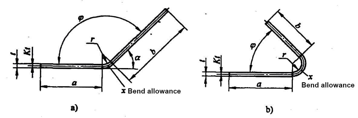
a) φ>90° b)≤90°
1) The bending tolerance table is applicable for sheet metal bending processes where no pressure plate is used and the plate width is greater than three times the thickness.
2) When bending on a press brake, calculations can be made according to this table.
3) According to the dimensions marked in the diagram, the calculation formula for the unfolded dimensions of the folded part is as follows:
i = a + b + x
In this equation,
- L – the unfolded dimensions of the folded part;
- a and b – the lengths of the straight sides of the folded piece as marked in the diagram;
- x – the bending coefficient of the bent part.
4) Due to the numerous factors that affect sheet metal bending, this sheet metal bending tolerance table should be used as a reference only.
- Bending tolerance values for bending angle φ=20°
- Bending tolerance values for bending angle φ=25°
- Bending tolerance values for bending angle φ=30°
- Bending tolerance values for bending angle φ=35°
- Bending tolerance values for bending angle φ=40°
- Bending tolerance values for bending angle φ=45°
- Bending tolerance values for bending angle φ=50°
- Bending tolerance values for bending angle φ=55°
- Bending tolerance values for bending angle φ=60°
- Bending tolerance values for bending angle φ=65°
- Bending tolerance values for bending angle φ=70°
- Bending tolerance values for bending angle φ=75°
- Bending tolerance values for bending angle φ=80°
- Bending tolerance values for bending angle φ=85°
- Bending tolerance values for bending angle φ=90°
- Bending tolerance values for bending angle φ=95°
- Bending tolerance values for bending angle φ=100°
- Bending tolerance values for bending angle φ=105°
- Bending tolerance values for bending angle φ=110°
- Bending tolerance values for bending angle φ=115°
- Bending tolerance values for bending angle φ=120°
- Bending tolerance values for bending angle φ=125°
- Bending tolerance values for bending angle φ=130°
- Bending tolerance values for bending angle φ=135°
- Bending tolerance values for bending angle φ=140°
- Bending tolerance values for bending angle φ=145°
- Bending tolerance values for bending angle φ=150°
- Bending tolerance values for bending angle φ=155°
- Bending tolerance values for bending angle φ=160°
- Bending tolerance values for bending angle φ=165°
- Bending tolerance values for bending angle φ=170°
4. Calculate unfold size with bend tolerance chart
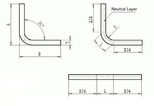
Fold forming 0°L=A+B-0.43T, T=Thickness, Deduction=0.43T
Formula: L (unfolding length) = A (outer size) + B (outer size) -K (K factor)
No 90° bend unfolded according to the neutral layer, the distance from neutral to the inner side of the sheet is T/3, inner R can refer to the above chart.
The width of the V die is 6 to 8 times the thickness of the plate
None-90° bend = 180°- Angle/90°*Deduction
The deduction is 1.8 times the thickness of the steel plate and 1.6 times the thickness of the aluminum plate.
For boards less than 2mm, the K factor is 0.432, R = board thickness, the unfolding size can be accurate to 0.05.
Generally, when designing the sheet metal parts, the minimum internal R = thickness / 2, if it is less than this, groove (V-cut) will be needed to solve the problem.