1. Introduction
In the manufacture of automotive exhaust pipes and similar tubular parts, quality problems such as wrinkles or tears often occur due to factors such as bend radius and material properties. It is particularly crucial to reduce or eliminate these problems in order to improve product quality and reduce waste rates.
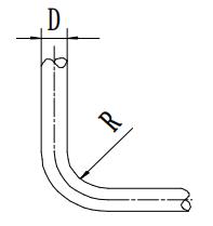
The bending process of tubes is comparable to that of sheet metal: the outer wall of the neutral layer is subjected to tensile stresses, thinning the wall, while the inner wall of the neutral layer undergoes compressive stresses, thickening the wall. Excessive deformation may cause cracking of the outer wall and wrinkling of the inner wall. Table 1 presents the minimum bending radii for steel tubes.
Table 1: Minimum bending radius (R) for steel tubes
|
Wall thickness | Minimum bending radius R |
| 0.02D | 4D | |
| 0.05D | 3.6D | |
| 0.10D | 3D | |
| 0.15D | 2D |
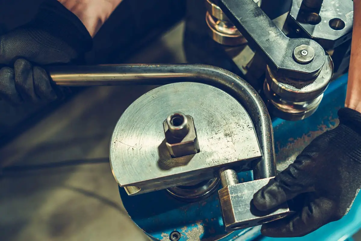
Pipe bending methods generally include: bending with hand pipe bending tools; bending with dedicated tube bending machines; anti-deformation bending method; cold extrusion bending; mold pressing to form elbows; hot extrusion bending of the central rod. This article mainly focuses on using dedicated tube bending machines as examples to analyze wrinkling and tearing problems.
two . The process of bending tubes using a dedicated tube bending machine.
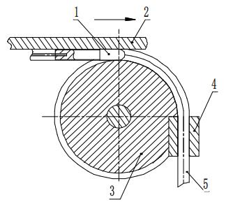
1. Chuck
2. Guide plate
3. Die
4. Pressure block
5. Tube component
The dedicated pipe bender typically uses a mandrel for bending. The process involves assembling the die, item 3, on a rotating spindle of the machine. Before the tube is bent, it is fixed in the die by the pressure block, item 4. A mandrel, item 1, is inserted into the tube. When the machine is started, the tube material gradually curves around the die to take shape.
3. Analysis of Control Elements and Corresponding Control Methods
3.1 Radius of Curvature
During the bending process, a smaller bending radius may cause wrinkling on the inner side or even cracks on the outer wall. The design must take into account the pipe wall thickness, external diameter and material properties. Table 1 should be consulted when choosing the bend radius.
Empirically, when using a regular cylindrical mandrel for bending, the minimum bending radius can be slightly smaller than that indicated in Table 1, as long as it does not cause wrinkling or cracking. When a smaller bending radius is required, the tube wall thickness can be increased, the outer diameter reduced, and a material with good ductility and a smooth exterior should be selected.
3.2 Chuck Shape and Clamping Position
3.2.1 Chuck Working Position
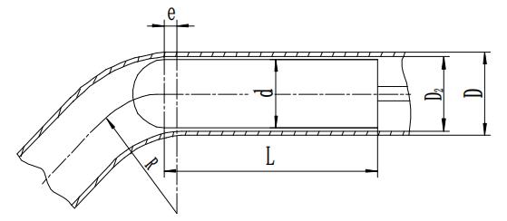
In tube core bending, the shape and operating position of the mandrel have a significant impact on the tube bending quality. Normally, the diameter d of the mandrel should be 0.5-1.5mm smaller than the inner diameter of the tube, making it easier to insert into the tube.
The distance e from the point where the mandrel enters the tube to the start of the bending process (see Figure 2) can be calculated using the following empirical formula.
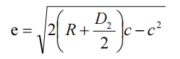
In the equation,
- e – the distance where the mandrel begins to bend inside the tube
- R – the radius of curvature of the central layer of the cross section
- D2 – the internal diameter of the tube
- c – the clearance between the internal diameter of the tube and the mandrel. Typically, c is chosen between 0.5 and 1.5 mm.
3.2.2 Chuck shape selection
There are several shapes of chucks, roughly divided into: standard cylindrical chucks, spoon chucks, wire chucks, and flexible shaft chucks. The standard cylindrical chuck is often used because of its simple structure, ease of manufacture and easy removal after bending.
However, since the contact area between the mandrel and the pipe wall is small, it is less effective in preventing the creation of an elliptical shape.
The length of the chuck, indicated as L, must be (see Fig. 2)
L = (3 to 5) d mm
When the diameter d of the mandrel is large, the coefficient assumes a smaller value and vice versa.
3.2.3 Checking the clearance between the mandrel and the inner wall of pipe fittings
If the gap between the mandrel and the inner wall of the pipe fittings is too large, at the beginning of the bending process, the mandrel and the pipe wall do not fully touch each other, causing severe wrinkling on the inner side of the pipe fittings, and the occurrence of dead curves. If the gap is too small, when fixing a normal welded pipe, the uneven height of the weld on the inner wall of the pipe connection may make it difficult to insert the mandrel into the pipe connection.
Through a long period of summarizing tube bending work, the author determined a more appropriate clearance between the tube inner wall and the mandrel:
c = D2 – d = 0.5 to 1.5 mm.
3.3 Guide plate speed adjustment
In standard tube bending operations on press brakes, guide plates (Figure 1) clamp the workpiece and move in sync with it. The speed of this guide plate is adjustable and its movement speed directly influences the quality of the bent tube.
The workpiece, fixed by the press block in the die, contains a mandrel inside it. As the machine operates, the tube material gradually curves around the die, with the guide plate advancing in sync with the speed of the die. During this process, static friction between the guide plate and the workpiece acts on the workpiece.
If the speed of the guide plate is greater than that of the die, it transmits a forward thrust to the workpiece; conversely, it applies a resistance force if its speed is lower. Bending tests show that, all things being equal, if the speed of the guide plate substantially exceeds the linear speed of the die, wrinkles tend to form on the inner wall of the tube.
On the other hand, if the speed of the guide plate is significantly delayed, the outer wall of the tube will become noticeably thinner, to the point of tearing. Therefore, effectively adjusting the guide plate thrust speed to match the die speed is crucial to ensure bending quality.
From this analysis, it is clear that the thrust speed of the guide plate must be synchronized with the bending speed during the bending process. Therefore, before bending or after switching to a die with a different bending radius, it is necessary to adjust the speed of the guide plate accordingly.
As shown in Figure 1, the bending speed α and bending radius R are predefined. The length of the arc that the bending die must rotate is calculated, i.e. the distance that the guide plate must advance synchronously at the same time. The press brake idles while the operator slowly turns the speed control valve lever, watching the guide plate move.
After bending to the set angle and stopping, the actual displacement of the guide plate is measured with a ruler, comparing it with the theoretical calculation. If they are different, the idle speed adjustment can be repeated until the measured value matches the calculated value.
In reality, due to load factors, the movement speed of the guide plate during actual bending is many times slower than that during idling. Therefore, when adjusting the guide plate thrust speed, the actual value may be slightly higher than the theoretical value.
4. Conclusion
In conclusion, the presence of wrinkles, tears or elliptical deformities in the tube is an important measure of the quality of the bend.
These quality defects can be minimized by selecting a suitable bending radius, an appropriate mandrel shape, controlling the clearance between the mandrel and the inner wall of the tube, adjusting the mandrel insertion position and the movement speed of the guide plate.