Preparation
Operator:
To carry out the rolling operation on a roll calender, it is essential that the equipment manager knows the structure and operation of the machine well.
The lamination process requires the assistance of two operators, where one supervises coordination and the other provides support. Both operators must work in unison to achieve a continuous rolling process for the cylinder.
Equipment:
Before using the laminator, it is essential to inspect its general condition. After starting the machine, check whether the hydraulic system pressure is normal and check whether the overturned side can be closed without problems. Before operating the machine, ensure that the bottom roller of the plate rollers is rotating correctly to confirm that the system is working properly.
Commissioning Plate Rolls:
Perform a visual inspection and make necessary adjustments to align the upper and lower rollers in a parallel position.
Adjust the center distance according to the roller parameters to achieve the appropriate distance.
When rolling a steel sheet, it is essential to ensure that its parameters, such as yield strength, minimum allowable rolling diameter, width and thickness, are within the parameters of the rolling mill.
Furthermore, the surface quality of the steel plate must be smooth and free from any visible defects along the cutting edge, flat, clean and without any initial layer or scratches.
Before rolling, the steel sheet must undergo appropriate heat treatment. For example, 45# steel requires annealing of the entire sheet, while low carbon steel should not undergo any heat treatment.
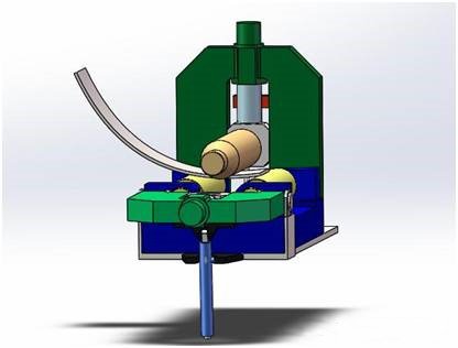
Pre-bending
Alignment :
Position the plate on the roll bender and use visual methods to align the top edge of the roll parallel to the cutting edge of the plate, ensuring any error is kept within the ±0.5mm range.
Rolling circular :
Apply continuous 15mm pressure to the outer circle of the upper roller against the plate surface. Control the rotation of the lower roller using a jog control. Stop the rotation of the lower roller when the arc length of the plate reaches 600-800 mm.
Apply 10 mm pressure to the upper roller, rotate the lower roller and stop when the end of the plate is tangent to the lower roller.
Repeat the process of pressing the upper roller and rotating the lower roller until the arc length of the pre-folded sheet matches the arc length of the sample.
Make sure that the pre-curved circular arc makes a smooth transition to the straight edge and avoid any dead curvature phenomenon to avoid difficulties in correcting the circularity during subsequent processing.
Apply the same pre-bending method to the other end of the board.
Circular bearing
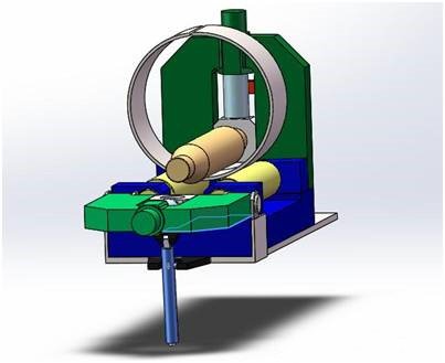
Pre-bending lamination
Before starting continuous rotation of the lower roller, apply continuous pressure of 15 mm to the upper roller based on the surface of the contact plate and rotate the lower roller. Confirm that all rollers are working properly.
(Note: To avoid accidents, do not use gear to drive the lower roller continuously during this procedure).
Operators must be cautious when starting the rolling mill. The auxiliary operator must provide timely and accurate commands and cooperate with the main operator in the case of any visual blind area for controlling the rolling machine.
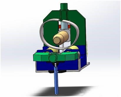
To roll a circle, press the upper roller repeatedly. When the distance between the two ends of the plate reaches 800mm, reduce the pressing pressure of the upper roller to 3-5mm each time until the two ends are close together.
During the circular rolling process, observe whether the plate is displaced. If the displacement (visual) exceeds 10 mm, stop the laminating process and reduce the error.
Solution: Lift the upper roller 30mm, move the plate in the opposite direction when the steel cylinder material is fully loosened, and then push the lower part to press the upper roller to the original position and continue rolling the circle.
Edge Alignment and Spot Welding: Generally, the edge of the cylinder will not be aligned.
The solution:
Lift the upper roller 5mm, place a 3mm steel plate mat under the travel position that contacts the lower roller, control the lower roller to move the pad to the position between the plate and the lower roller.
Press the upper roller for 3-5mm to make the left and right migration move in the alignment direction.
Properly control the lower roller to align the circular surface (measured by sample or ruler).
After confirming qualified alignment, spot weld the corresponding position. The spot welding must be free from defects, and the position of the spot welding must be strong and effective.
Circular lamination without pre-bending

The lamination process is identical to the pre-bending lamination described previously.
During the entire rolling process, there should be no noticeable occurrence of dead bending.
Before spot welding, make sure that the two straight edges of the plate are straight or slightly inward (concave ≤ 10 mm) when the two ends of the plate are joined.
Welding
When working with carbon steel such as Q235A, it is recommended to use a welding machine with CO2 gas shielding. The welding process must be carried out in a well-grooved and clean welding area.
It is important to ensure that the surface of the welded joint is less than 3 mm and that the residual height of the welded joint is uniform. If the height exceeds the standard, it must be reduced by sanding until it is less than 3mm, and the weld must be uniform. The welded joint must also be free from surface defects.
In the case of medium carbon steel, such as 45#, it is necessary to round and anneal the material after welding. The rolling and welding procedure for medium carbon steel is the same as for low carbon steel.
When working with special materials, it is essential to follow a specific process.
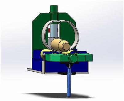
Rounding correction
- Roundness correction of roll bending machine
To begin, place the completed welding cylinder on the plate bending rollers and turn the side roller. Make sure the center of the cylinder is aligned and parallel to the roller centerline of the platen rollers. Additionally, position the cylinder in the center of the rolling mill to receive hydraulic pressure evenly.
Before performing rounding correction without pre-bending, roll the flat parts separately back and forth. Each time, the pressing distance should be 3-5 mm until the roundness is consistent with the sample using a visual method.
Then roll the cylinder welding joint down and adjust the upper roller down to make contact with the cylinder. Slowly lower the top roller and roll back and forth, starting with a lower pressure, usually no more than 15mm. Thereafter, the cylinder should not exceed 10 mm per roll.
(Refer to cylinder pressing distance for one rolling cycle = diameter * plate thickness / 10000).
The maximum lower circle correction upper roller distance (refer to maximum cylinder pressure = diameter * plate thickness / 3000) can be increased or decreased accordingly with the actual need, but generally not exceeding 20% of the reference value.
When the lower distance reaches the perfect condition, roll five more circles to even out the tension. Then measure the circularity of the inner circle at the location below the horizontal diameter.
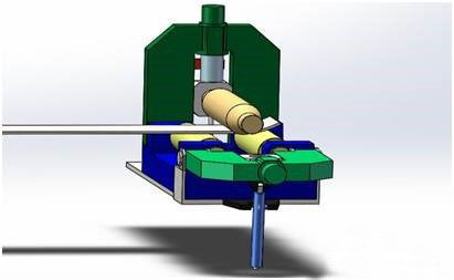
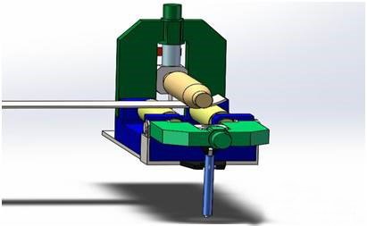
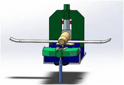
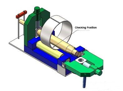
Lower the amount into place after rolling five turns to ensure that the cylinder tension is evenly distributed. Measure the cylinder diameter circle by lowering the level (clockwise 7-8 or 4-5 for the hour hand) as shown in the figure below:
If the circularity of the cylinder is consistent after measuring the entire circle, the upper roller can be lifted.
When lifting the upper roller, this should be done slowly, increasing the distance by no more than 5 mm per turn, usually 2-3 mm. After 3-4 turns, the upper roller should no longer come into contact with the cylinder.
Measure the roundness with a tape measure. Generally, the roundness should be less than 10mm, which can be considered acceptable. However, additional manual correction of the circle may be necessary to meet drawing specifications.
- Artificial rounding correction :
Typically, the flame heating method is used for roundness correction.
Before performing roundness correction, use a sample or tape measure to mark the maximum and minimum sizes, as well as the position of the arch. It is important to ensure that marks are accurate and easily visible.
To correct circular arcs and size unqualified positions, heat them with a flame. For thick sheets, it is recommended to use a large electric flame for heating. When the temperature reaches about 600-700°C (in the case of Q235 low carbon steel), use point or linear heating to generate a temperature difference in the direction of the thickness of the steel plate. This will lead to local deformation and help to obtain the desired roundness correction.
After the heated position has cooled, measure it using a sample and measuring tape. If the measurement is not within the specified tolerances, an artificial circular correction method must be employed to bring it into line with the drawing requirements.