In recent years, with the substantial reduction in the prices of lasers and laser welding heads, the application of laser welding has increased, and it is also being used in the welding of control cabinets.
Compared to the traditional arc welding process, switchgear arc welding is less efficient and requires substantial post-welding processing.
The advent and promotion of laser welding technology has broken this impasse, not only improving welding efficiency but also eliminating the need for post-welding grinding.
High-quality weld beads have enabled significant advancement in the control cabinet welding process. This article introduces the three main integration technologies of distribution panel cabinet laser welding unit, jig and laser welding process.
Unit Integration Technology
Switchgear welding units typically employ robotic welding and dedicated welding machine layouts for unit integration.
Layouts for dedicated welding machines generally correspond to one or a few types of parts, with low flexibility and high costs. In contrast, robotic welding is more flexible, can accommodate a variety of part sizes and specifications, and is relatively cost-effective.
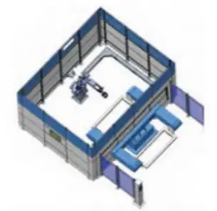
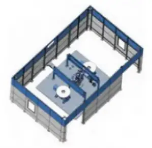
The most commonly used layout is the dual-station robotic laser welding unit. This unit usually consists of a six-axis robot, dual-station rotary positioner, laser and protective cabin.
Manual loading is used, and internal welding and external loading and unloading are carried out, thereby improving equipment utilization and production efficiency. This is currently the most common unit arrangement for switchgear welding.
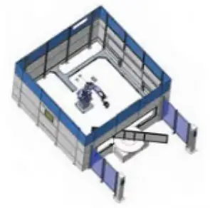
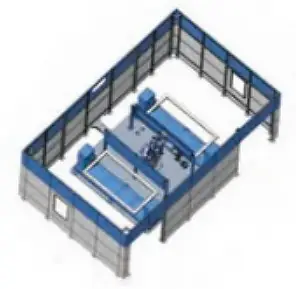
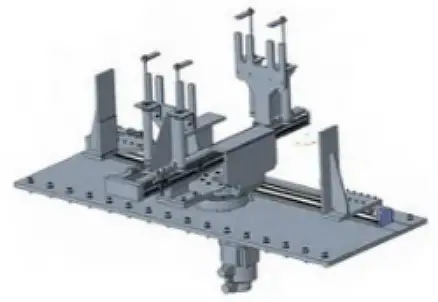
As shown in Figure 1, the rotary positioner is generally equipped with adjustable clamping jigs to meet the welding requirements of different specifications, offering great versatility. Depending on the customer's different welding process requirements, the unit shapes in Figures 2 and 4 can also be configured.
Automatic jig technology
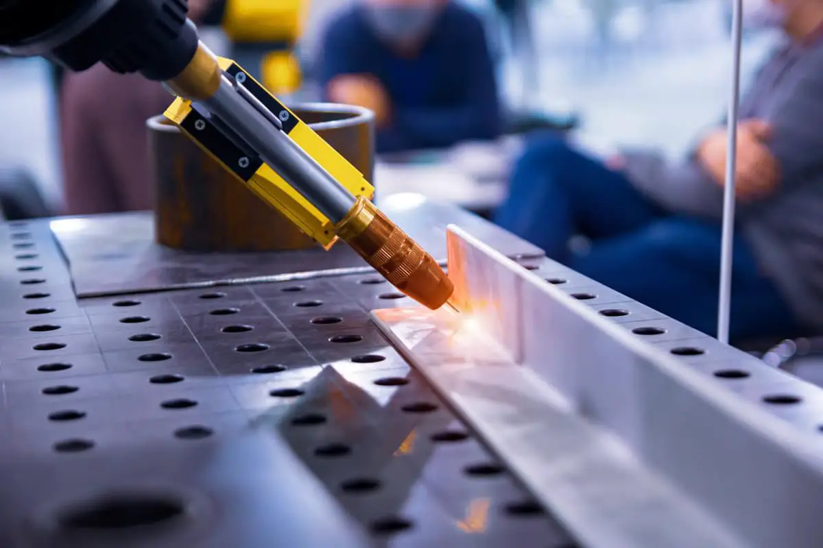
At present, switch cabinet welding generally adopts arc welding; Individual parts are spot welded before being subjected to continuous welding.
Spot welding is typically performed manually or with spot welding jigs, while continuous welding generally employs robots or dedicated linear module machines using continuous welding jigs.
Manual spot welding places high skill requirements on workers, as it must ensure both the space between welding seams and the consistency of spot welding.
The quality of the pre-weld spot welding affects the dimensional accuracy and weld seam quality of the subsequent overall cabinet welding.
Spot welding jigs are generally used to ensure the clearance and quality of welding seams, but their use significantly affects welding efficiency and is not suitable for large-scale welding.
Figure 5 shows a switch cabinet spot welding jig, where the slide rail is manually adjusted to accommodate various specifications for cabinet spot welding.
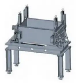
Figure 6 shows a switch cabinet continuous welding jig, which positions the spot welded part, fixes it using a cylinder and linear module, and performs continuous welding of various specifications of cabinets through a linear module and rotary module.
Automatic jigs can achieve automatic clamping, positioning and welding of individual parts, but require larger spatial dimensions, structural layouts, transmission and control.
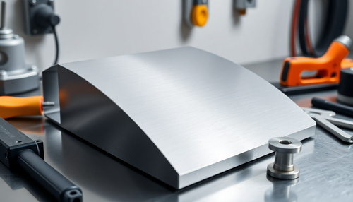
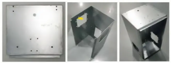
A typical switchgear cabinet is generally composed of three subcomponents, including the cabinet fold plate and two side seal plates. The sheet thickness is generally just 1.5mm (varying according to the manufacturer) of carbon steel sheet, as shown in Figure 7.
Switchgear enclosures come in a variety of specifications and sizes, and all are thin boards. To perform laser welding, the internal support of the bent plate of the cabinet must first be resolved, while ensuring that the internal support prevents parts after welding. The internal support and external pressing must be able to automatically adjust based on different specifications and sizes.
For large-sized parts, the issues of intermediate auxiliary support and clamping rigidity must be considered, as well as resolving the consistency of long gaps in the weld seams and the repetitive positioning accuracy of the part's welding location.
There should be no excessively large seams that could cause problems with the strength and quality of laser welding.
Finally, through a restricted spatial structure design, space must be left for welding, allowing the robot to weld in the most ideal posture.
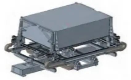
Figure 8 shows an automatic switch cabinet laser welding jig, which can perform functions such as internal support, avoid parts and external pressing for different cabinet sizes and specifications.
Laser welding process
In addition to ensuring assembly clearances and welding seam positioning accuracy through accessories, the part structure must be adjusted appropriately to meet the requirements of the cabinet laser welding process.
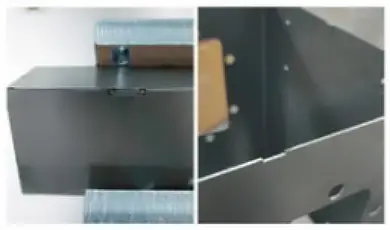
By adding positioning grooves to the bending plate and end plate in the preliminary stage, the welding quality of the cabinet in the later stage has improved significantly.
However, the size of the groove will affect the quality of subsequent welding seams. Through testing, we have achieved a satisfactory groove size. When carrying out batch testing under this groove size, the strength and aesthetics of the welding seams met the customer's requirements, as shown in Figure 10.
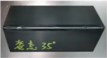
By employing laser fillet welding, the need for post-weld grinding is eliminated, improving welding efficiency and cabinet aesthetics. However, fillet welding places strict requirements on the focus distance and welding incidence angle.
A large amount of welding tests have shown that the self-fusing fillet requires a large spot to cover the top and bottom plates, hence a large blur. By obtaining the same spot size, the welding position of the 300mm focus welding head is further away from the protective lens, which is safer.
Simultaneously, under negative defocus, the 300mm focus welding head can be paired with the coaxial blowing component of the 200mm welding head, ensuring that the welding seam is still protected by the gas under large defocus.
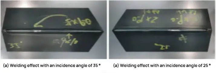
Extensive testing has shown that changing the clearance angle to 35° produces the best welding results. Figure 11 compares the effects of welding at different angles of incidence.
Wrap it up
(1) Distribution cabinet body laser welding uses a dual-station robotic laser welding unit to achieve internal welding and external loading and unloading, improving equipment utilization and production efficiency.
(2) Distribution cabinet body laser welding is equipped with a dedicated automatic fixture, enabling all functions such as internal support for different specification sizes, parts avoidance and external fixing.
(3) Laser welding of the distribution cabinet body adopts a positioning slot structure and fillet welding process, eliminating the need for post-welding grinding, improving the welding efficiency and aesthetics of the cabinet, and solving the problem of poor welding quality of the distribution cabinet body.