INTRODUCTION
Pneumatic grinder is a metal grinder designed to cut/grind metal by applying pneumatic pressure. The machines are intended exclusively for mass production and represent the fastest and most efficient way to cut metal. Low speed operation occurs in a grinding operation. This machine is a multifunctional machine.
See too :
Automatic Pneumatic Grinding Machine Mechanical Design 1
WORKING PRINCIPLE
As pneumatic circuit plays a vital role in this device, it is very necessary to explain the working of this circuit.
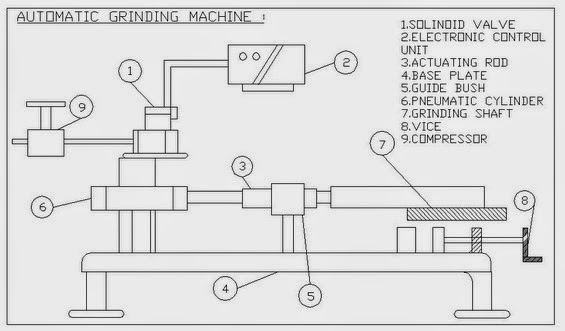 automatic pneumatic grinding machine
Starting initially with air packs, their function is to compress air from a low inlet pressure (usually atmospheric) to a higher pressure level. This is achieved by reducing the air volume.
Air compressors are generally positive displacement units and are of the reciprocating piston type or rotary screw or rotary vane type. The air compressor used here is a two-stage compressor unit, typically small in size. It also consists of a compressed air tank, electric rotor and pulley drive, pressure controls and instruments for quick connection and use. The compressor is driven by a 10 HP engine and designed to operate in the range of 145 – 175 PSI. If the pressure exceeds the design pressure of the receiver, a supplied release value releases the excess air and thus prevents any danger that may occur.
The stored air from the compressor passes through an air filter where the compressed air is filtered of fine dust particles. However, before air is sucked into the compressor, a filtration process takes place, but not enough to operate in the circuit where the filter is used. It then has a pressure regulator where the desired pressure is adjusted to the operator. Here a variable pressure regulator is adopted. Through a variety of available direction control values, a manually operated solenoid valve with control unit is applied. The solenoid valve used here has 5 ports and 3 positions. There are two exhaust ports, two outlet ports and one inlet port. In two extreme positions only the directions can be changed while the Center ore is in a neutral position and no physical changes occur. The 2 output ports are connected to an actuator (Cylinder). The pneumatic drive is a double-acting, single-rod cylinder. The cylinder output is coupled to another purpose. The piston end has an air horn effect to prevent sudden thrusts at the ends.
WORKING PRINCIPLES
- Compressed air from the compressor reaches the solenoid valve. The solenoid valve changes the flow direction according to the signals from the timing device.
- Compressed air passes through the solenoid valve and is admitted to the front end of the cylinder block. The air pushes the piston into the grinding stroke. At the end of the grinding stroke, air from the solenoid valve reaches the rear end of the cylinder block. The pressure remains the same but the area is smaller due to the presence of the piston rod. This puts greater pressure on the piston, pushing it at a faster rate, thus allowing for a faster return stroke.
- The weight attached to the end of the saw frame provides constant loads that lower the saw to allow continuous grinding of the work.
- The piston stroke length can be changed by making a suitable adjustment to the timer.
- The grinding saw frame is removed in case of grinding operation. The same procedure as above is taking place in the rectification operation.
FORMS
BENEFITS :
LIMITATIONS
- Only smaller size and soft metal can be cut
- It is more expensive than the mechanical saw because of the compressor unit.
- Less efficiency when compressed in a mechanical device.
- Air leakage affects the operation of the unit.