Abstract –
The function of the governor is to maintain the speed of an engine within specified limits whenever there is a change in load. This device can be used in almost all vehicles. The aim of our investigation is to identify the areas of stress concentration and areas that are most susceptible to failure when the governor is rotating around its axis, and also the value of these stresses is measured. This analysis is carried out with the help of PRO E. The displacement of the different SPINDLE elements in relation to the base is also calculated and the graphs are plotted. The “ARMS WEIGHT” effect is the main area of concern in our study and all calculations are made considering the weight of the arms. The weight of the arms acts on the centroid of the arms and when the governor assembly rotates, the centrifugal force begins to act on the centroid of the arms and tends to deflect the arms, this deflection or flexion must be minimized. In our work, we have done stress analysis on a particular governor mounting configuration and then various materials are suggested on theoretical basis.
Centrifugal regulator
An engine-driven flyweight mechanism is attached to the throttle and works against a spring in a similar manner to the pneumatic governor, resulting in essentially identical operation. A centrifugal governor is more complex to design and produce than a pneumatic governor. However, the centrifugal design is more sensitive to speed changes and is therefore better suited to engines that experience large fluctuations in load.
GOVERNOR'S PROJECT
Design process
- Governor Design Criteria All legs move exactly like each other
- Its total axial deflection at 6000 rad/s cannot exceed 2.3 mm.
- Neglecting the effects of in-plane load, the fundamental natural frequency will be less than 2,000 Hz
- The lengths L1 and L2 have the following relationships: 1.4*L2
- <= L1 <= 2.0*L2. L1 and L2 must be reasonable and comparable. The width and thickness of all leg sections are constant.
- The thickness and width of each leg can vary in 0.25mm increments
- The thickness is relatively small
- The height of the short leg sections is 4 mm.
- All edges of the legs (except those that connect to the shaft) are straight
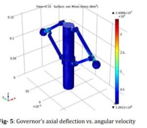 governor axial deflection
RESULTS AND DISCUSSION
From the tension analysis of the different parts of the governor assembly we were able to identify the tensions. Governor axial deflection vs. angular velocity, the angular velocity of the model was varied and the radial displacement was obtained. For various angular velocities, the nature of the deviation in radial displacement was obtained. And from our study we determined that as the angular velocity increases, the axial displacement increases.
Reference Report and Download: