1 . Scope
1.1 This procedure is applicable to CNC tube bender used for cold bending of metal tubes.
1.2 This procedure is applicable to single-head hydraulic bending machines models DW63 and DW114 in the agricultural equipment structural parts workshop.
two . Normative reference documents
The following documents are essential for the application of this document. For dated reference documents, only the dated version applies to this document. For undated reference documents, the most recent version applies to this document.
GB/T 28763-2012 CNC Pipe Bending Machine
3 . Terms and definitions
CNC tube bending machine : A tube bender that must have at least three-axis motion, including spindle rotation, mandrel linear motion, and mandrel rotation, and is controlled by a CNC system.
4 . Tube bending machine parameters
4.1 The main parameter of the tube bender is the maximum outer diameter of the tube.
4.2 The main parameters and basic parameters of the pipe bending machine must comply with the rules prescribed in the table below.
| Parameter name | Maximum tube outer diameter/mm | Maximum Pipe Wall Thickness/mm |
| Parameter value | 10 | 1.2 |
| 16 | 1.2 | |
| 25 | 3 | |
| 38 | 4 | |
| 42 | 4 | |
| 60 | 5 | |
| 63 | 5 | |
| 76 | 5 | |
| 89 | 6 | |
| 114 | 8 | |
| 159 | 12 | |
| 168 | 12 | |
| 219 | 16 | |
| 273 | 20 |
When the outer diameter is greater than or equal to 114 mm, it is 0.4 to 1 times the maximum radius of the bent tube.
4.4 Parameters of tube bending machine for structural parts workshop:
| Pipe Bending Machine Model | Tube External Diameter (mm) | Pipe wall thickness (mm) | Bend radius (mm) |
| DWFB63 | 19 to 63 | ≤5 | 50 to 250 |
| DWFB114 | 48 to 114 | ≤8 | 100 to 750 |
5. Existing tube bending dies in the structural components workshop
| type of material | Material specification mm | Wall Thickness mm | Radius of curvature (default as median) mm | Matching equipment |
| Squared pipe | φ16 | two | 58 | DWFB63 |
| φ25 | two | 50 | DWFB63 | |
| φ25 | two | 150 | DWFB63 | |
| φ33 | 3 | 101.5 | DWFB63 | |
| Φ35 | 4 | 60 | DWFB63 | |
| Φ42 | 3 | 100 | DWFB63 | |
| Φ48 | 3.5 | 130 | DWFB63 | |
| Φ50 | 6 | 100 | DWFB114 | |
| Φ60 | 5 | 150 | DWFB63 | |
| Φ60 | 5 | 200 | DWFB63 | |
| Φ60.5 | two | 150 | DWFB114 | |
| Round tube | 30×30 square tube | two | 220 | DWFB114 |
| Square tube 40×80-8 | 2.5 | 100 | DWFB114 | |
| Square tube 40×80-8 | 3 | 180 | DWFB114 | |
| Square tube 40×80-8 | two | Outer diameter: 220 | DWFB114 | |
| 50×50 square tube | 2.5 | Inner diameter: 170 | DWFB114 | |
| Square tube 50×70-7 | 2.5 | 120 | DWFB114 | |
| Square tube 50×70-7 | 3 | 120 | DWFB114 | |
| Square tube 60×80-6 | 4.5 | 150 | DWFB114 | |
| Square tube 60×80-8 | 4.5 | 150 | DWFB114 |
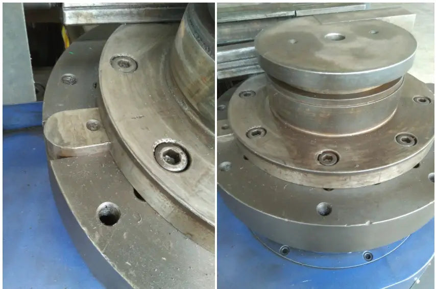
6. Mold Installation and Adjustment
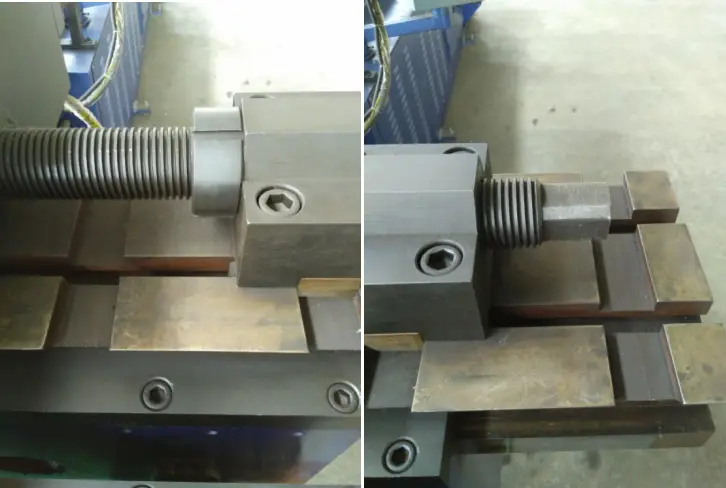
6.1 Main Mold Installation
6.1.1 Place the folding wheel mold with the key slot facing down into the corresponding key of the fixed seat. After placing it horizontally, adjust the wheel mold left and right so that the screw hole of the wheel mold matches the screw hole of the fixed seat.

6.1.2 Tighten the fixed nut, there should be no play.
6.2 Installation and Adjustment of Pressing Molds
6.2.1 Attach the pressing die to the slider with screws, rotate the adjusting screw, move the clamping die up and down, align the center of the pressing die with the center of the bending die groove to ensure a perfect fit between the two while feeding the mold from the press, without any interference.
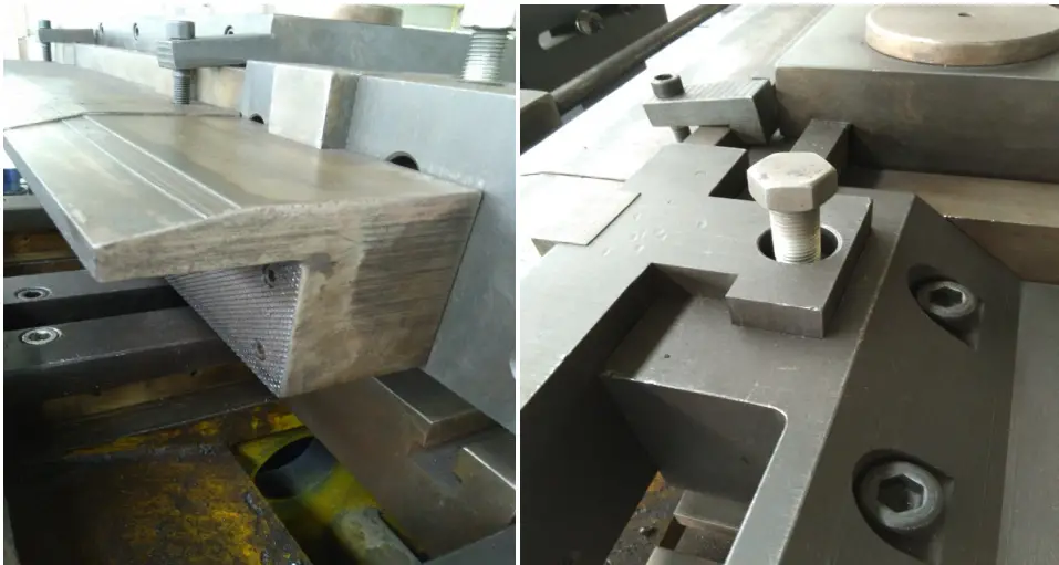
6.2.2 Loosen the pressure mold slider fixing nut, and then use a wrench to loosen the slider adjusting screw.
6.2.3 Place a test mold material about 300 mm long into the bending groove of the wheel mold. Control the pressure mold to clamp the tube forward and there should be no loosening. Tighten the pressure mold slider adjustment screw with a wrench. Control the pressure mold to retract, and then retighten the pressure mold slider adjustment screw half a turn with a wrench. Finally, tighten the pressure mold slider fixing nut.
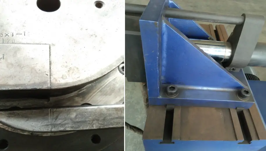
6.3 Installation and Adjustment of the Fixing Template
6.3.1 Connect and fix the clamping mold and slider with screws. Turn the adjustment screw, move the clamping mold up and down to make it the same height as the main clamping mold.
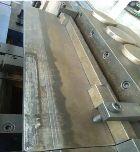
6.3.2 Loosen the clamp die slider fixing nut and use a wrench to loosen the slider adjustment screw.
6.3.3 Place a test mold segment approximately 300 mm long into the groove of the wheel mold tube and tighten the mold clamp slider adjustment screw with a wrench to secure the tube. There should be no loosening. Remove the tube from the test mold, use the wrench to further tighten the mold clamp slider adjusting screw by 1/3 turn, and tighten the mold clamp slider fixing nut.
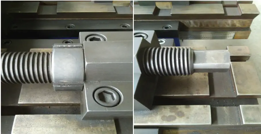
6.4 Installation and adjustment of the central rod
6.4.1 Connect the threaded hole of the central rod with the screw of the central rod drawbar. After tightening, adjust the rear seat of the center rod draw bar so that the tangent position of the arc surface on the center rod in the horizontal direction does not cross the center line of the bending die.
7. Calculation and Cutting of Bent Tubes
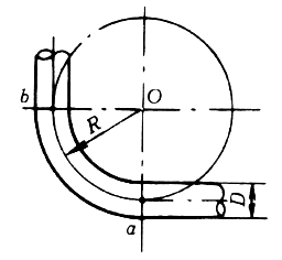
7.1 Calculation for tubes bent at 90°
For cold drawn bent tubes, consider R=(4~6)D. As shown in Figure 1-3, after the tube is bent, the lengths of the outer arc and inner arc of the bent segment are not the actual length of the original straight tube, but only the length of the center line of the bent tube. remains unchanged before and after bending.
Its unfolded length is equal to the length of the original straight section of the tube. Now suppose the start and end points of the folded section are a and b, respectively. When the bending angle is 90°, the length of the bent section of the tube is exactly 1/4 of the circumference of the circle drawn with r as the radius. The length of your arc is represented by the radius of curvature, which is:
Arc length ab=2πR/4=1.57R
From formula (1-3), it can be known that the unfolded length of the 90° curvature is 1.57 times the radius of curvature.
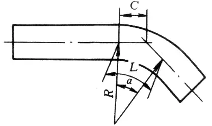
7.2 Calculation of Arbitrary Bending Tube
An arbitrary curvature tube refers to a tube with an arbitrary angle and radius of curvature. The unfolded length of the folded part of this tube can be calculated using the following formula:
L=παR/180=0.01745αR
In the formula, L is the unfolded length of the folded part (mm); α— is the flexion angle (°); π— is Pi; R is the radius of curvature (mm).
In addition, the calculation of the unfolded length of any flexible pipe segment can also be performed according to Figure 1-6 and Table 1-1.
The following example illustrates how to use Table 1-1.
Table 1-1 Calculation of arbitrary pipe bending
| Bending angle | Half flexion length C | Bending length L |
| 1 | 0.0087 | 0.0175 |
| two | 0.0175 | 0.0349 |
| 3 | 0.0261 | 0.0524 |
| 4 | 0.0349 | 0.0698 |
| 5 | 0.0436 | 0.0873 |
| 6 | 0.0524 | 0.1047 |
| 7 | 0.0611 | 0.1222 |
| 8 | 0.0699 | 0.1396 |
| 9 | O.0787 | 0.1571 |
| 10 | O.0875 | 0.1745 |
| 11 | 0.0962 | 0.1920 |
| 12 | 0.1051 | 0.2094 |
| 13 | 0.1139 | 0.2269 |
| 14 | 0.1228 | 0.2443 |
| 15 | 0.1316 | 0.2618 |
| 16 | 0.1405 | 0.2793 |
| 17 | 0.1494 | O.2967 |
| 18 | 0.1584 | 0.3142 |
| 19 | 0.1673 | 0.3316 |
| 20 | 0.1763 | 0.3491 |
| 21 | 0.1853 | O.3665 |
| 22 | 0.1944 | 0.3840 |
| 23 | 0.2034 | 0.4014 |
| 24 | 0.2126 | 0.4189 |
| 25 | 0.2216 | 0.4363 |
| 26 | 0.2309 | 0.4538 |
| 27 | 0.2400 | 0.4712 |
| 28 | 0.2493 | 0.4887 |
| 29 | 0.2587 | 0.5061 |
| 30 | 0.2679 | 0.5236 |
| 31 | O.2773 | 0.5411 |
| 32 | 0.2867 | O.5585 |
| 33 | O.2962 | 0.5760 |
| 34 | O.3057 | 0.5934 |
| 35 | 0.3153 | 0.6109 |
| 36 | 0.3249 | O.6283 |
| 37 | O.3345 | 0.6458 |
| 38 | O.3443 | O.6632 |
| 39 | 0.3541 | O.6807 |
| 40 | 0.3640 | 0.6981 |
| 41 | 0.3738 | 0.7156 |
| 42 | 0.3839 | O.7330 |
| 43 | 0.3939 | 0.7505 |
| 44 | 0.4040 | 0.7679 |
| 45 | 0.4141 | O.7854 |
| 46 | O.4245 | 0.8029 |
| 47 | 0.4348 | O.8203 |
| 48 | 0.4452 | O.8378 |
| 49 | 0.4557 | 0.8552 |
| 50 | 0.4663 | O.8727 |
| 51 | 0.4769 | O.8901 |
| 52 | 0.4877 | 0.9076 |
| 53 | 0.4985 | O.9250 |
| 54 | O.5095 | 0.9425 |
| 55 | O.5205 | 0.9599 |
| 56 | 0.5317 | 0.9774 |
| 57 | O.5429 | 0.9948 |
| 58 | 0.5543 | 1.0123 |
| 59 | O.5657 | 1.0297 |
| 60 | 0.5774 | 1~0472 |
| 61 | 0.5890 | 1.0647 |
| 62 | 0.6009 | 1.0821 |
| 63 | 0.6128 | 1.0996 |
| 64 | O.6249 | 1.1170 |
| 65 | 0.6370 | 1.1345 |
| 66 | 0.6494 | 1.1519 |
| 67 | 0.6618 | 1.1694 |
| 68 | 0.6745 | 1.1868 |
| 69 | O.6872 | 1.2043 |
| 70 | 0.7002 | 1.2217 |
| 71 | 0.7132 | 1.2392 |
| 72 | O.7265 | 1.2566 |
| 73 | O.7399 | 1.2741 |
| 74 | 0.7536 | 1.2915 |
| 75 | 0.7673 | 1.3090 |
| 76 | 0.7813 | 1.3265 |
| 77 | 0.7954 | 1.3439 |
| 78 | O.8098 | 1.3614 |
| 79 | O.8243 | 1.3788 |
| 80 | 0.8391 | 1.3963 |
| 81 | 0.8540 | 1.4173 |
| 82 | O.8693 | 1.4312 |
| 83 | O.8847 | 1.4486 |
| 84 | 0.9004 | 1.4661 |
| 85 | 0.9163 | 1.4835 |
| 86 | 0.9325 | 1.5010 |
| 87 | 0.9484 | 1.5184 |
| 88 | O.9657 | 1.5359 |
| 89 | 0.9827 | 1.5533 |
| 90 | 1,000 | 1.5708 |
Observation:
When using the values of C and L from the table, they should be multiplied by the radius of curvature R. For example, given that the bending angle of the elbow in Figure 1-7 is 25°, the radius of curvature R=500mm, and the distance from the installed pipe section to the turning point M is 911mm, if you take a straight pipe to make the elbow, how should you mark the line?
Solution:
The length of the straight section of the pipe at the end of the pipe to be processed, b = 911-CR
From Table 1-1, when the angle is 25°, C=0.2216, L=0.4363; therefore, CR is: 0.2216R=0.2216×500=111mm. Thus, b=911-111=800 mm
The actual unfolded length of the folded part L=0.4363R=0.4363×500=218 mm
Based on the calculated lengths of the straight section of the pipe b and the unfolded length L of the folded piece, you can then mark the line. As shown in Figure 1-7b.
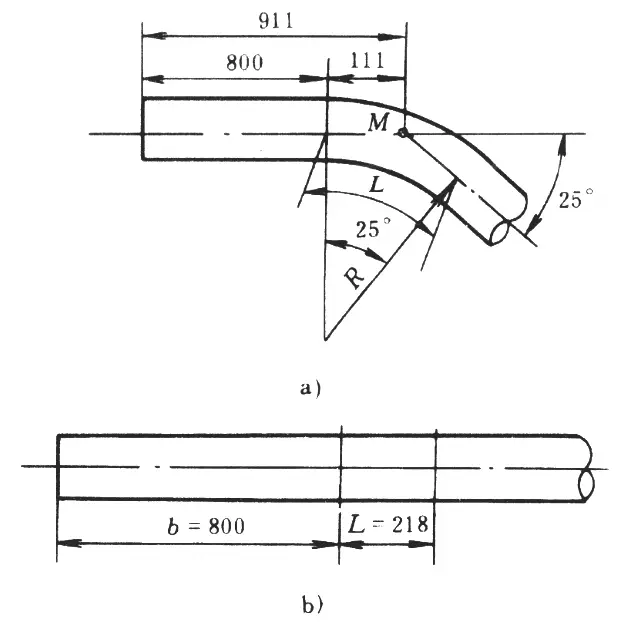
From the above examples, as long as the bending angle and radius are defined, Table 1-1 can be used for convenient pipe bending calculations of any angle and radius.
8 . Preparations before starting the machine
8.1 The tube bending machine must be operated by specially trained personnel. Unauthorized operation by third parties is prohibited.
8.2 Operators must wear protective equipment before operation and carefully inspect the machine and the working environment. Check the surroundings of the workplace and remove all objects that may interfere with work and traffic.
8.3 Before operation, first check whether there is a lack of oil at each lubrication point, whether the moving mechanism is loose, and whether the safety protection device is reliable. After confirmation, the operation can be carried out; Hard objects and pipe fittings should not be used to touch the main control screen.
8.4 After the machine is started, it must run empty 1-2 times before normal operation. If the machine has been inactive for several days, it must be turned on for ten minutes before normal operation.
8.5 Various molded materials must use corresponding molds and must not be mixed or misused. Only one shaped material can be bent at a time; It is not allowed to fold two or more overlapping materials to avoid damage to equipment and molds.
9 . New parts debugging and mass production
9.1 For the first production of parts, prepare models as references. After the molds are installed and debugged as necessary, and the materials are cut according to the theoretical cutting length, mark the bending points, perform bending operations on the material, and compare the bent parts with the template.
If there is an error, adjust the cutting length and bending points until there is no error between the bent part and the template, then you can save the cutting size and template program. The next time you make this type of workpiece, you can directly access the saved data for pipe bending.
9.2 For mass-produced parts, prepare models as references. Access the saved cut size and template program, make one part first, and then compare the first part to the template to determine if there are any errors.
If there is an error, adjust the cutting size and template program until there is no error between the bent part and the template, then you can save the data for mass production.
10 . Common pipe bending defects and preventive measures
10.1 Severe flattening on the outer side of the arch
During the cored pipe bending process, select the appropriate mandrel (if necessary, a flexible mandrel assembled from multiple sections can be used), install it correctly, and ensure that the pipe groove axis of all The components are in the same horizontal plane when installing the mold.
10.2 Grinding on the outside of the arch
To avoid excessive grinding, a common effective method is to use a pipe bender with a side reinforcement device or a back thrust device.
By increasing or pushing, part of the resistance during pipe bending is compensated, improving the stress distribution in the pipe cross-section, moving the neutral layer outward, thus achieving the objective of reducing the thinning of the pipe's outer wall.
10.3 Cracks on the external part of the arch
First, make sure the pipe material has a good heat treatment status, then check whether the pressure of the clamping mold is too high and adjust it to an appropriate pressure.
Finally, make sure there is good lubrication between the mandrel and the tube wall to reduce bending resistance and friction between the inner tube wall and the mandrel.
10.4 Wrinkling inside the arch
Appropriate measures should be taken according to the location of the wrinkles. If the front cutting point is wrinkled, the mandrel position should be adjusted forward to obtain reasonable support for the tube during bending.
If the back cutting point is wrinkled, a wrinkle prevention block must be installed to ensure correct positioning and adjust the die pressure to an appropriate level.
If the entire inner side of the arc is wrinkled, it indicates that the diameter of the mandrel used is too small, causing too large a gap between the mandrel and the tube wall, or the die pressure is too low, which cannot make the tube fits tightly to the bending die and the wrinkle prevention block during bending.
Therefore, the chuck must be replaced and the clamping die adjusted to provide adequate pressure on the die.


