With advances in vehicle weight reduction and crash safety, the use of high-strength steel plates in the automotive industry is gradually increasing.
Currently, flexible high-strength plate parts are mainly used in structural components of automobile chassis.
Sheet metal bending can be done in two ways:
(1) Stamping Folding
This bending technique requires that the bending die and sheet material be fully adhered to each other and precisely match the sheet metal parts.
Due to the high mold development cost, it is suitable for sheet metal parts with complex structures.
(2) Press Brake Bending
This method eliminates the need for the bending die to match each piece of sheet metal individually.
By adjusting the bending process and the stroke of the press brake, a flexible bending mold can be produced to accommodate the requirements of various bent parts.
It is economical for sheet metal parts with simple structures as the development cost of a press brake mold is low.
However, when high-strength plates are bent using the free bending method in a press brake, production efficiency is reduced due to various defects caused by factors such as material performance, equipment conditions and bending process parameters. .
This may result in economic losses.
In this article, we will analyze the main types of defects in the free bending of high-strength steel sheets and propose corresponding improvement measures and countermeasures.
Bending Crack
When the internal radius of curvature (R) is reduced to a certain extent, excessive deformation may result in cracks or microcracks of the lateral longitudinal material outside the sheet material in the radius of curvature, as illustrated in Figure 1.
During the initial phase of trial production of high-strength steel bent parts, flexural cracking defects are a common occurrence, leading not only to wastage of the plate, but also to an obstacle to the normal progress of the project.
The main factors that contribute to cracking in bent high-strength steel parts can be attributed to the following aspects.
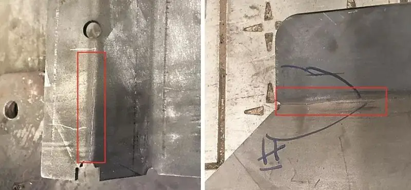
Fig 1 Cracks in the radius of curvature of bent high-strength steel parts
radius of curvature
The minimum bending radius, which prevents cracking of the outer fiber, is the final bending radius.
The minimum bending radius depends on several factors, including the mechanical properties of the material, the grain direction of the board, the surface quality of the board, the edge quality, and the thickness of the board.
As the material's strength increases, its plasticity decreases, resulting in a larger minimum radius of curvature.
Furthermore, cold-rolled plates tend to exhibit anisotropy, with greater plasticity along the grain direction than perpendicular to it.
Therefore, when the bending line is perpendicular to the grain direction of the sheet, the minimum bending radius is smaller.
To avoid flexural cracks or microcracks, it is essential to accurately predict the minimum bending radius of the sheet material in advance.
For example, the bending radius of BP500 protective steel (with a yield strength of not less than 1250MPa) should be at least 4 times the thickness of the material, and the bending line should be perpendicular to the fiber direction of the sheet material.
To avoid flexural cracks caused by an insufficient radius of curvature, it is crucial to consider the relationship between the radius of curvature and the minimum radius of curvature, as well as the relationship between the line of curvature and the grain direction of the sheet material during digital-analog review phase.
Bending line positioning method
In the bending process, it is important to correctly position the bending line to ensure the accuracy of the bent parts.
Traditionally, manual line positioning methods include manual or laser marking positioning, process notch positioning and machine tool block positioning.
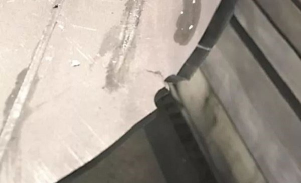
FIG. 2 Process Gap Crack of High Strength Plate Bent Parts
During the bending test of BP500 sheet materials, when the process notch positioning method is used, cracks may occur in the positioning gap, as shown in Figure 2.
The notch treatment changes the original shape of the material's smooth edge to a sharp shape, causing the stress to concentrate in the gaps. When the sheet material is bent, the stress value in the gap exceeds the strength limit and cracks occur.
This highlights the high surface and edge quality requirements of BP500 sheets during the bending process. The surface must be free from cracks, scratches, burrs and nicks on the edges.
Therefore, the BP500 plate cannot be positioned for bending using the process notch positioning method.
It is recommended to use the undamaged sheet metal machine tool block positioning method for bending.
Doubling Springback
Backward bending spring refers to the situation where the bending angle and radius of the bent parts are different from the intended values after being removed from the press brake tools.
The resilience of flexed parts is mainly influenced by the following factors:
- Mechanical properties of the material
- Relative radius of curvature ratio (r/t)
- Bending method
- Flexion angle at center
- Shape of the folded pieces.
The size of the elastic return angle is proportional to the flow resistance and hardening index of the material, and inversely proportional to the modulus of elasticity.
The yield strength of BP500 shielding steel is not less than 1250 MPa, therefore its springback tendency is greater than that of ordinary steel plates.
Main methods for improving the accuracy of bent parts:
- Change the local structure of folded parts
- Choose materials with low flow resistance and a large modulus of elasticity
- Replace free bending and mold compensation with correct bending
The improvement of the bending springback of the BP500 plate was mainly achieved through the mold compensation method, since the reinforcement plate could not be added to the bending position due to limitations in the shape of the bending parts.
Table 1 shows the results of experiments carried out on bending BP500 plates with a curvature radius of 20 mm and central curvature angles of 90°, 120° and 135°, respectively.
Table 1 The relationship between bending spring back angle and center bending angle for BP500 plate
| Central angle flexion | Springback angle |
|---|---|
| 90° | 14th |
| 120° | 18° |
| 135° | 21° |
As shown in the table, it can be seen that as the central bending angle increases, the resilience also increases.
In the process of designing the bending die for the BP500 material, a compensation of 14° for the springback angle (for a bending angle of 90°) was made in the press brake tools.
The mold was designed with a negative angle to optimize the bending resilience of the BP500 plate and improve the precision of the bent parts.
Figure 3 illustrates the structure of the lower bending matrix before and after springback compensation.
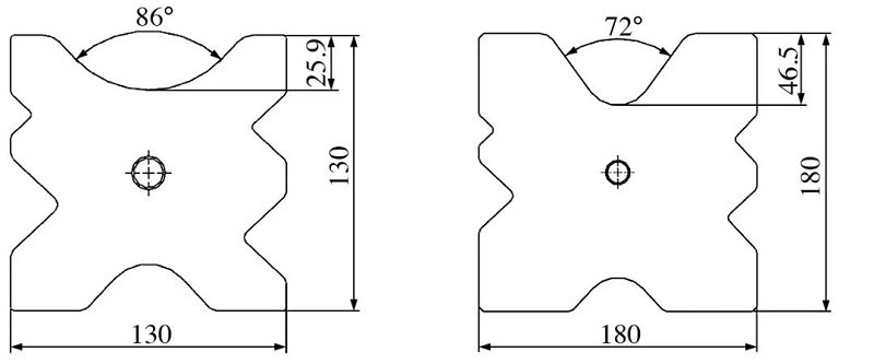
FIG. 3 Schematic diagram of the lower bending die
Deformation of the bent section
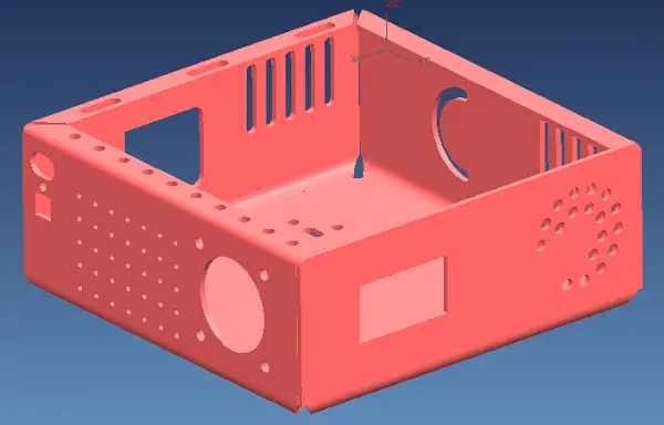
Due to modeling requirements, some bent parts have large holes close to the bend line, as illustrated in Figure 4(a).
After the drilling process is completed, the bent parts are deformed near the hole, affecting the installation of other parts.
To solve this problem, the drilling method of large holes has been adjusted. Part of the hole was drilled, while part of the connecting strip was retained, as shown in Figure 4(b).
After the bending process was completed, the rest of the hole was processed.
This method significantly improves the warping problem, improves the flatness of bent parts, and ensures proper installation of parts.
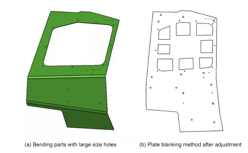
FIG. 4 Large hole suppression method for bending parts
Inconsistent Bending angle
In the bending process of BP500 material, it was found that the bending angles of the left and right ends of the parts with long bend lines were inconsistent.
The reasons for this inconsistency are as follows:
- When the press brake ram reaches the final bending position, the parallelism between it and the table surface exceeds the tolerance.
- The parallelism between the upper die mounting surface and the lower working surface exceeds tolerance.
- The degree of parallelism between the V-shaped groove of the lower bending die and the lower installation surface exceeds the tolerance.
- The thickness of the folded plate is inconsistent at the left and right ends.
Even when the lower bending die was rotated 180°, the angular difference between the left and right sides of the bent parts still existed and the value had been switched.
Further investigation revealed that the size of the circular arc on the bottom working part of the bending punch was not consistent, leading to poor parallelism between the bottom surface of the installation and the bottom working surface of the bending punch.
This resulted in inconsistent camber angles from left to right.
By reprocessing the circular arc on the bottom working surface of the bending punch, the flatness was improved to 0.05 mm/m, and the problem of inconsistent bending angles between the left and right ends of the bent parts was solved.
Conclusion
In conclusion, when bending a high-strength plate, it is important to determine its minimum bending radius and springback tendency through experimentation.
Based on these findings, it is necessary to ensure the accuracy of the press brake, the precision of the mold and the uniformity of the plate thickness.
Further optimization and adjustment of the bending technique of the press brake, such as optimizing the positioning method, can help to effectively reduce defects in the bending of high-strength plates and improve the product passing rate.