The proper cutting sequence is divided into two parts: cutting the inner hole of the component and cutting the edge of the component.
The appropriate cutting sequence for internal component holes should follow the principle of first cutting the interior and then the exterior, starting with smaller holes before larger ones, cutting round holes before irregular shaped ones, and starting with more complex shapes before simpler ones. .

Inside before outside
When there are multiple holes in the board components, it is advisable to start by cutting the middle hole first and then work your way outward step by step. This helps ensure that the cutting heat is evenly radiated outward.
Small before big
This means that when internal hole sizes vary, it is recommended to start by cutting the smaller holes first. Cutting smaller holes generates less cutting heat, resulting in less thermal impact on the workpiece.
Circle first then square
When cutting circular holes, the uniformity of the circle allows for a relatively balanced external emission of cutting heat. However, for square holes, the balance of external cutting heat emission is noticeably insufficient.
The thermal stress arising from the cutting heat has a significant impact on the displacement and deformation of components.
Cross jump
When cutting dense holes, skipping cuts rather than continuously cutting in a sequential manner can help reduce the impact of stress generated by cutting heat on components.
Complex before simple
When drilling holes of different shapes in the board, it is recommended to start with holes with a complex shape and then move on to simpler ones.
Profile and edge cutting
Selection of the initial profile cutting point
The selection of the starting point for cutting the profile is directly related to the cutting sequence. If conditions permit, closed ring cutting should be preferred. This means that there should be no cut openings on the remaining edge of the material.
In cases where the thickness of the material is large and the edge of the material cannot be cut, a cutting line with control function can be used. By restricting the cutting lines with control function, the cutting deformation is limited.
Cutting lines with a control function have a geometric characteristic where the end is smaller than the front.
When there is no edge, measures must be taken to select the cutting point position and cutting direction.
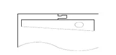
Figure 1
Forced fixation
Forced clamping methods, such as weight pressing, are commonly employed in profile cutting to restrict movement of components or raw materials.
In NC cutting, the stop iron limit method is generally used to control the displacement phenomenon.
Bilateral simultaneous cutting
This method is suitable for simultaneous gas cutting of several narrow and long blanks on a single steel plate. It is an effective way to control bending deformation during the gas cutting process.
Bilateral simultaneous cutting
This method is suitable for simultaneously cutting multiple narrow and long blanks on a single steel plate using gas cutting. It is an effective way to control bending deformation during the gas cutting process.
Timely cooling
Timely cooling can effectively control deformation.
When NC cutting is used on a Q235 plate with a thickness of 6 mm, a length of 6 m and a width of 50 mm, applying a water cooling method approximately 50 mm behind the spacer can significantly reduce bending deformation.
It is important to immediately adopt the water quenching method while considering the sensitivity of gas cut steel to water quenching to avoid cracks or hardened structures caused by excessive watering.
End Limit Method
When cutting long, narrow strips from a steel plate manually or semi-automatically, it is recommended to create long holes of (3-5)mm * (50-80)mm at both ends of the cutting line. This preparation will help reduce bending deformation of the strip cut pieces, allowing for more accurate cutting along the intended line.
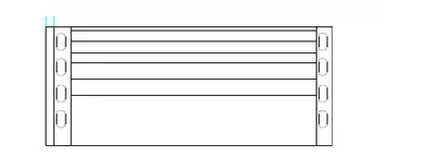
Figure 2
Collision and dent
As the thickness of the gas cutting plate decreases to 8 mm or less, the shrinkage and deformation of the cutting edge becomes more and more pronounced. To minimize bulging or depression during the cutting process, heavy objects can be placed on the board to suppress and control these effects.
Cutting range
Interval cutting involves leaving a length of 10~30mm after cutting a certain length in the cutting process before making another cut. This method is highly effective in controlling displacement during cutting.