In recent years, the sheet metal bending process has seen rapid development in the railway transportation industry as it is an essential processing method.
Accuracy in the dimensional aspects of the bending process is crucial for sheet metal processing companies as bending is a comprehensive cold working process.
This post uses theoretical analysis of sheet metal parts bent at 90° to deduce the K-factor calculation method and explains the scope of its application. It provides engineers and technicians in the sheet metal industry with a theoretical basis and practical reference.
K Factor Calculation for Sheet Metal Bending
In the bending process, the outer layer of the metal sheet is subjected to tensile stresses while the inner layer undergoes compressive stresses.
Between the outer and inner layers is a transition layer known as the neutral layer, which does not undergo tensile or compressive stress.
The length of the neutral layer remains constant before and after bending, making it an important factor in calculating the unfolding size of the sheet metal.
Figure 1 is a schematic illustration of the dimensions involved in bending sheet metal.
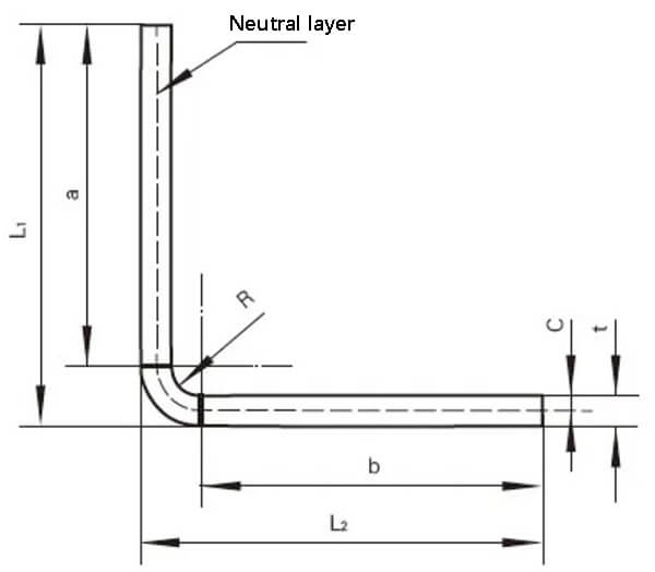
Fig. 1 Schematic diagram of sheet metal bend size
As shown in Fig. 1, the unfolding size of the metal sheet is set to L, so there are:
l=a+b+2π(R+C)/t ①
L1=a+R+t ②
L2=b+R+t ③
Where K factor: 0
Derived from equations ① ~ ④, it can be obtained that:
K=2(L-L1-L2+2R+2t)/πt – R/t ⑤
The results obtained in equation ⑤ show that the value of the K factor depends on the overall dimensions, internal bending diameter and material thickness of sheet metal parts.
Traditional manual calculation of sheet metal unfolding
Traditionally, sheet metal technicians would create a sheet metal unfolding CAD drawing based on the bending coefficient derived from years of bending experience. They would then draw the unfolded shape of the sheet metal, export it in DXF format, and insert it into a laser cutting machine to obtain the unfolded shape of the part.
In this traditional manual calculation method, the bending coefficient can vary between different processing facilities.
As an example, consider the rear cover of a power cabinet for an electric locomotive, made of 1.5 mm thick cold-rolled steel sheet, as shown in Figure 2. A processing plant would calculate its expansion size as follows form:
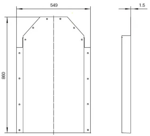
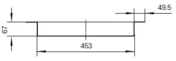
Fig. 2 Dimensional diagram of the rear cover of a power cabinet
Total width = 453 + 67 × 2+49.5 × 2-8 × 1.5 (material thickness) + 4 × 0.5 (bending factor) = 676 mm
Total length = 860 + 67-2 × 1.5 (material thickness) + 0.5 (bending coefficient) = 924.5 mm
Calculation of sheet metal unfolding using 3D modeling software using the K-Factor method and its range of application
The manual drawing process has low efficiency.
By using three-dimensional modeling software and the K-factor method, the efficiency of sheet metal unfolding calculation is significantly improved.
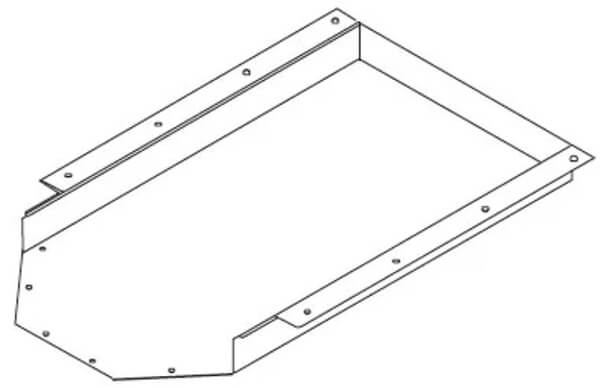
Fig. 3 3D view of the back cover of a power cabinet
Using the traditional manual method of calculating the unfolded size of sheet metal, the unfolded size and the inner bending diameter are input into equation ⑤ to determine the corresponding K factor.
During the sheet metal bending process, a smaller inner bending diameter results in greater compression and tension in the inner and outer layers of the material. If the yield strength of the material is exceeded, cracking and fractures may occur.
For example, the rear cover of a power cabinet for an electric locomotive in Figure 2 has an internal bending diameter of 1.5 mm, and the corresponding K-factor calculated using equation ⑤ is 0.486 when using three-dimensional modeling software .
Similarly, the K factor for other thickness specifications can be calculated.
Table 1 lists the bending parameters used by a sheet metal processing company.
Table 1 SolidWorks Bending Parameters
| Material thickness (mm) | K Factor | Bending inner diameter (mm) |
| 1.5 | 0.486 | 1.5 |
| two | 0.486 | two |
| 3 | 0.486 | 3 |
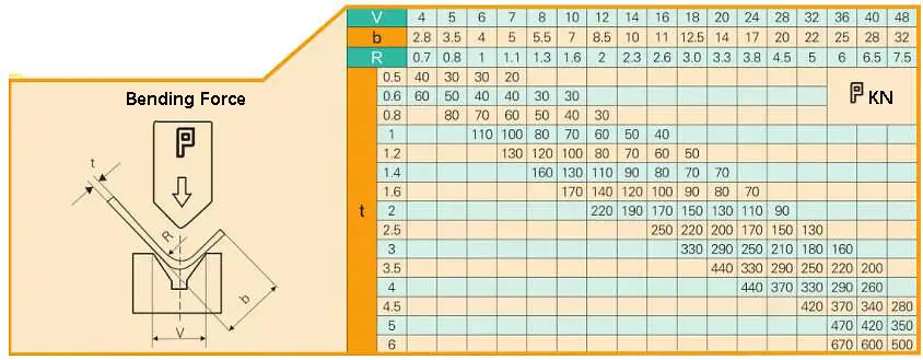
Fig. 4 Bending force quick check table of bending machine
The result of the K factor calculation can be input into the 3D modeling software.
However, when the software is used for direct expansion, gaps may occur in the expanded drawing, such as those seen in the expanded local drawings I and II in Figure 5.
These gaps must be corrected to meet laser cutting requirements, as shown in Figure 6.
3D modeling software can also export DXF drawings with bend lines to aid in subsequent bending processes.
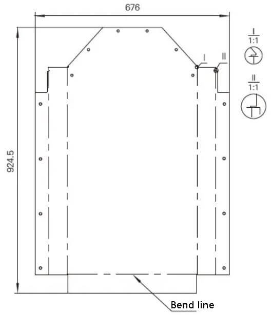
Fig. 5 Enlarged view of the power cabinet rear cover exported directly by the 3D modeling software
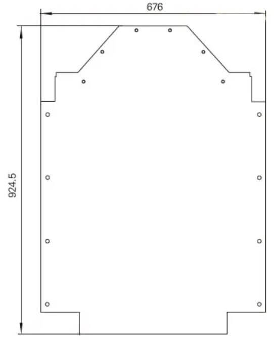
Fig. 6 Modified expanded view
Analysis of the bending process
The shapes of the bending tools are shown in Figure 7.
When processing, appropriate tools are chosen based on the shape of the workpiece.
Most processing companies have a wide range of bending tools, especially those with a high level of specialization.
To bend various complex sheet metal parts, many customized bending tools of various shapes and specifications are used.
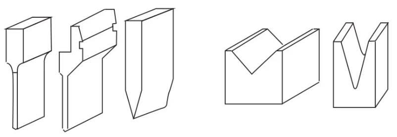
Fig. 7 Bending tool
Many factors can affect the bending process, including the arc radius of the upper die, material properties, material thickness, strength of the lower die, size of the lower die and so on.
To meet product requirements and ensure press brake safety, sheet metal processing companies have standardized their bending dies.
It is important to have a general understanding of the available flexural matrices during the structural design process.
As seen in Figure 7, the left side represents the upper matrix and the right side represents the lower matrix.
The basic principle of bending is to use the bending knife (upper die) and V-groove (lower die) of the bending machine to shape the sheet metal parts.
Bending Accuracy:
One fold: ±0.1mm
Two folds: ±0.2mm
Three-fold: ±0.3mm
and so on.
Conclusion
Using the K-factor method in three-dimensional modeling software for sheet metal unfolding calculation results in highly accurate unfolding drawings that can be exported directly. This eliminates the need for sheet metal unfolding technicians to redesign unfolding drawings, improves the processing efficiency of sheet metal production companies and shortens the delivery cycle.