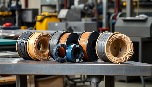
Hemming (flattening) is a method of frequent bending operation that typically involves bending the edge of a workpiece into parallel or rounded edges, as illustrated in Figure 1.
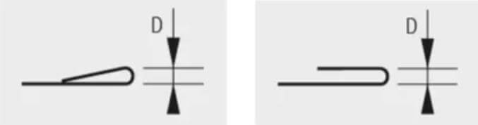
Figure 1 Schematic diagram of hemming and folding
The purpose of hemming and bending is to remove sharp edges, increase the strength of the workpiece, and improve its appearance.
The flattening bending process typically involves two steps:
(1) Pre-bend the workpiece by 30°, and then flatten and bend the workpiece as shown in Figure 2.
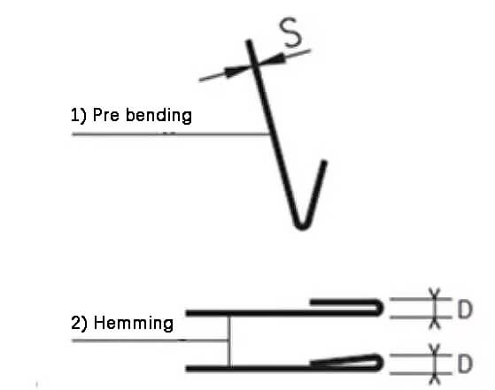
Fig. 2 Hemming and folding steps
To choose the correct flattening solution, you must first consider the material and thickness of the workpiece and the frequency of flattening.
(2) It is important to note that the hemming die can also be used for regular bending when hemming is not required.
There are two types of sheaths:
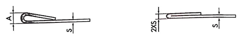
- PARTIAL FLATTENING: the plate is thickened with little force, so the elastic return generates a teardrop shape between the flat side and the rest of the plate (see image above on the left)。
- FLATTENING: the plate is completely thickened (see image above right)。
The graphs on the right show the force required to produce the two types of sheath described above.

- Column 1: S = Sheet metal thickness
- Column 2: A = flattening height
- Column 3: Force required per meter to flatten sheet metal with 450N/mm 2 tensile strength (mild steel), 1 T = 9.8 KN
- Column 4: flatten metal sheet with 700N/mm 2 tensile strength (stainless steel)
There are four different hem bending solutions to suit different bending conditions:
(1) Flat bottom hemming die;
(2) U-shaped sheath die;
(3) Spring-type sheath die;
(4) Hydraulic hemming table.
Related: V and U Shaped Bending Strength Calculator
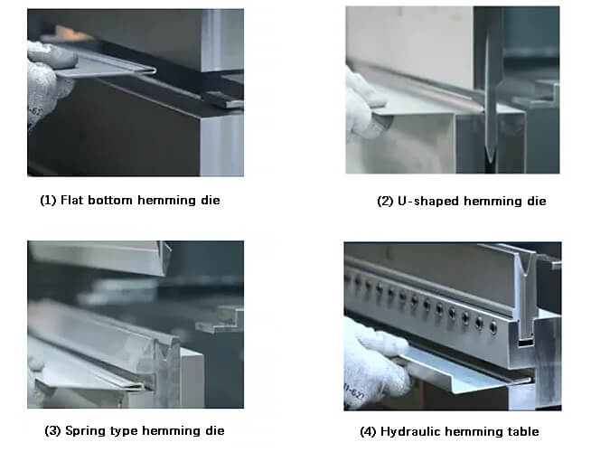
Fig. 3 Four hemming and folding solutions
1. Flat Bottom Hemming Die
The flat bottom hemming die performs hemming and bending through the use of two sets of dies, that is, a set of upper and lower standard dies and a set of upper and lower flat bottom dies are employed together, as illustrated in Figure 4.
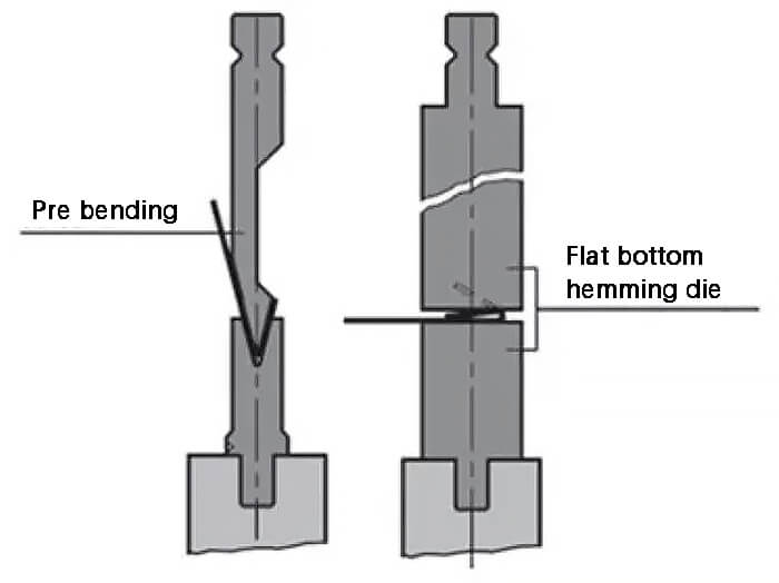
Fig. 4 Schematic diagram of sheath die with flat bottom
The process begins with pre-bending the part at 30° using a standard die.
Then the workpiece is flattened and bent into the flat-bottom die.
As the flat bottom hemming die requires a two-step bending process, it is mainly suitable for working conditions where hemming and bending are infrequent and offer good value for money.
However, there is some lateral force during hemming and the maximum thickness of the flattened carbon steel plate is limited to 2mm.
To solve the limited thickness in flat bending, a ball-type movable flat bottom die was innovatively introduced. The maximum thickness of flat carbon steel plate or stainless steel plate can now reach 4 mm, as shown in Figure 5.
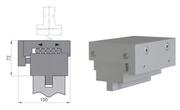
Fig. 5 Schematic diagram of the ball-type movable lower die
2. U-shaped hem die
A set of U-shaped hemming dies can be used to pre-bend and flatten, as illustrated in Figure 6.
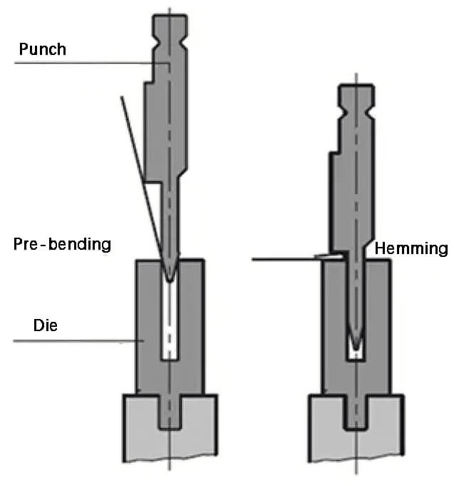
Fig. 6 Schematic diagram of the U-shaped sheath array
The benefit of the U-shaped hem die is its versatility; When not necessary for hemming and folding, it can be used for standard air folding, offering high usage and savings.
The maximum thickness for a flat carbon steel plate is 1.5mm, while the maximum thickness for a flat stainless steel plate is 1mm. The minimum flange size that can be flattened is approximately 14 mm.
3. Spring-type hem die
The spring sheath die comprises a standard 28° upper die and a 30° sheath lower die. The lower matrix sheath insert is supported by a spring.
During the hemming process, the pre-bent part is placed between the hemming insert and the guide insert of the lower hemming die. The hemming insert follows the descent of the upper die and presses down until the pre-folded part is flat.
The maximum thickness that the spring sheath die can flatten into a carbon steel plate is 2mm.
Like the other hemming solutions, the spring-loaded hemming die can also be used for standard air bending when not used for hemming bending.
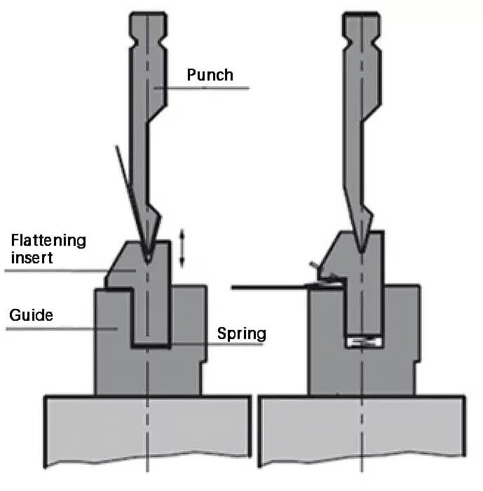
Fig. 7 Schematic diagram of the spring sheath matrix
4. Hydraulic hemming table
The hydraulic hemming table (as illustrated in Figure 8) operates similarly to the spring-loaded hemming die, but instead of a spring, a hydraulic cylinder is used to control the elevation of the sheath insertion.
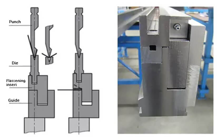
Fig. 8 Schematic diagram of the hydraulic sheathing bench
The oil pressure is 100 bar, which allows thicker and heavier parts to be bent. To further increase the service life of the hydraulic hemming table, a hardened hemming insert can be added.
The standard bottom die can be placed on the hydraulic hemming bench, and the V-opening can be selected according to your needs, up to a maximum of 40mm. The lower die can be clamped manually or automatically for more efficient die changes.
The hydraulic hemming table is capable of flattening carbon steel sheets with a thickness of up to 3 mm. The spring hemming die or hydraulic hemming table can be fixed on the fixture or the mechanical compensation table.
The hydraulic hemming table can also be installed directly on the bottom beam of the press brake, which provides greater opening height and flexibility.
Conclusion
In conclusion, each of the four different hemming and folding solutions has its own advantages. Depending on the hemming and folding application scenario, you can choose the appropriate solution.