Metal sheets are bent and formed using a plate bending machine. The workpiece is placed in the machine and the lifting lever is used to lift the brake block, which allows the workpiece to be positioned. The brake block is then lowered onto the workpiece and the bending lever is pressed to bend the sheet metal.
The minimum bending radius is determined by the ductility and thickness of the metal being formed. For aluminum sheets, the bending radius must be greater than the thickness of the sheet.

Due to elasticity, the bending angle of the metal is slightly greater than the required angle.
Sheet metal bending is typically performed in a metal processing shop. Sheet metal processing involves a series of techniques such as bending, riveting and welding of metallic materials.
Common problems that occur during this process and their corresponding solutions are discussed below.
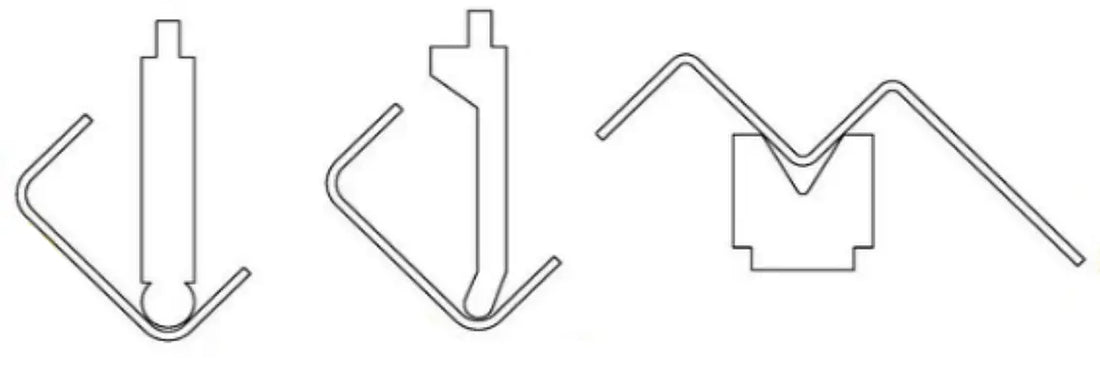
1. Challenges in bending groove and multi-fold parts
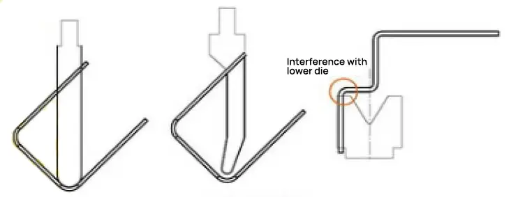
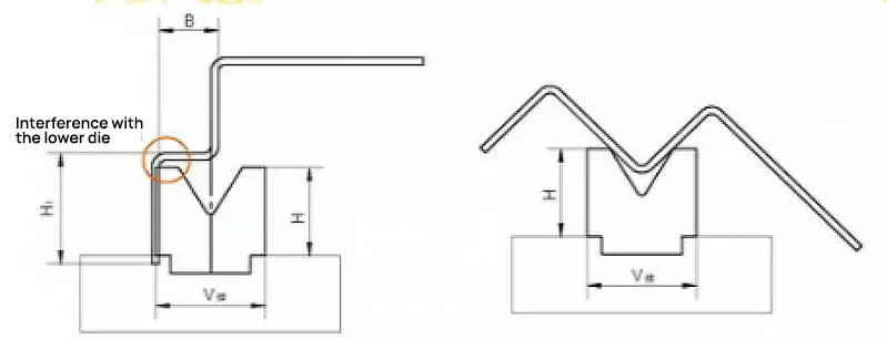
During the bending process of these parts, the width of the groove is greater than the height of the leg, causing interference between one end of the part and the upper die or slider of the press brake. This makes it impossible to guarantee the dimensions of the part, as shown in Figure 2.
Predicting Interference in Sheet Metal Bending
When dealing with high-leg precision sheet metal parts, determining whether bending can be completed requires several calculations, with the corresponding dimensions indicated in Figure 3.
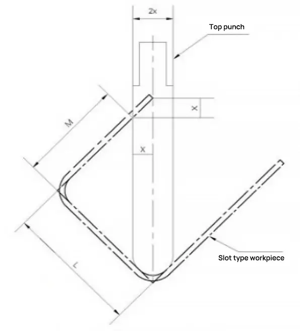
If LM<1.5x, the part can be bent without interference. If LM>1.5x, the workpiece cannot be bent, as this will cause interference.
Solutions to interference problems
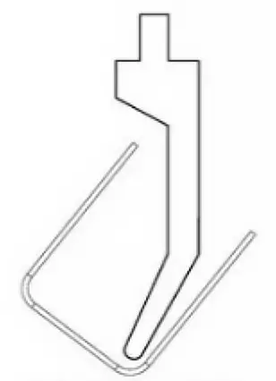
(1) If a groove-type workpiece suffers from bending interference, a gooseneck top die can be selected for bending. This avoids interference between the bending edge of the part and the press brake or upper die, ensuring the bending dimensions of the part, as shown in Figure 4.
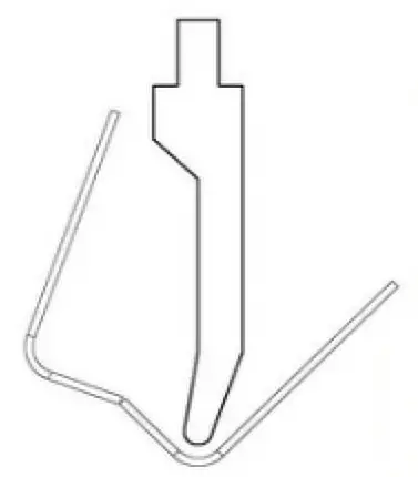
(2) If a groove-type workpiece suffers from bending interference and no suitable gooseneck top dies are available, reverse pre-bending can be performed mid-bending without affecting usage requirements, as shown in Figure 5. By artificially increasing the bending angle, the part can be bent normally. Then, a flat tire die can be used to press the pre-bending area to ensure that product quality requirements are met.
(3) When folding workpieces with multiple folds, if H1>H or B
① Select a high-dimensional bottom die with H>H1 to ensure the normal bending of the workpiece;
② Select a lower die opening with B>V/2 to ensure normal bending of the workpiece;
③ If there is no high-dimensional bottom die, change the bending sequence. Pre-deform the middle bend to a certain angle, then bend on the short side, form the third bend, and finally clamp the middle bend to the required size and angle, ensuring the process size of the part, as shown in Figure 6.
2. Bending Cracking
(1) Cause Analysis
Often, bending cracks occur on the tensile surface of sheet metal parts during bending, damaging the mechanical properties of the part and not meeting the usage requirements, leading to part dismantlement and economic loss. The main reasons are:
① Sheet metal has a special crystal structure and rolling grain direction, and bending parallel to the grain direction can easily cause fracture;
② The chosen radius of curvature R is too small;
③ The R angle of the V-shaped groove of the bottom die is small;
④ Material performance is poor.
(2) Preventive Measures
① When cutting, rotate the sheet to cut in the direction perpendicular to the bend (that is, the bending direction of the material is perpendicular to the grain);
② Increase the R angle of the upper die;
③ Use a lower die with a large R angle for processing;
④ Choose high-performance materials.
3. The folded edge is not straight and the size is unstable.
Cause analysis:
- no line pressing or pre-bending.
- inadequate material pressure
- dissymmetrical convex-concave die fillet and uneven bending pressure
- low height
Solutions
- design line pressing or pre-bending techniques
- increase lifting strength
- Uniform gap in convex-concave die and polished fillet
- make the height greater than or equal to the minimum size
4. The workpiece is scraped after bending.
Cause analysis:
- uneven material surface
- radius of curvature of convex matrix too small
- very small bending clearance
Solutions
- improve the smoothness of the concave matrix
- increase the radius of curvature of the convex matrix
- adjust the bending gap
5. There are cracks at the bending angles
Cause analysis:
- very small bending radius
- grain of the material parallel to the bend line
- worksheet burr extending outward
- poor remodelability of the metal
Solutions
- increase the radius of curvature of the convex matrix
- change the suppression layout
- making burrs on the inner fillet of the workpiece
- annealing or using soft material
6. Bending causes deformation of the hole
Cause analysis:
When elastic bending is used to position the hole, the outer part of the bending arm is pulled by friction on the surface of the concave mold and the outer surface of the workpiece, deforming the positioning hole.
Solutions
- employing form bending
- increase coverage pressure
- add an etching blanket to the cover plate to increase friction and prevent the workpiece from sliding when bending
7. The bending surface is thinner
Cause analysis:
- very small convex-concave mold fillet
- very small convex-concave matrix gap
Solutions
- increase the fillet radius of the convex-concave matrix
- adjust the clearance of the convex-concave matrix
8. The surface of the workpiece is protruding or uneven
Cause analysis:
Under tension in the circumferential direction, the outer surface of the material shrinks while the inner surface stretches during bending, forming bulges in the direction of bending.
Solutions
- provide adequate pressure to the convex-concave die in the final stamping stage
- make the radius of the concave round angle equal to that of the outer circle of the workpiece
- optimize techniques
9. The concave part is irregular at the bottom
Cause analysis:
- uneven material
- small contact area between cover and material or inadequate lifting force
- no material support device in the concave die
Solutions
- leveling materials
- adjust the material supporting device and increase the lifting force
- increase or correct material support device
- increase modeling processes
10. The axes of the holes on both sides are misaligned after bending
Cause analysis:
The rebound of the material changes the curvature angle, misaligning the center line.
Solutions
- increase the correction process
- improve the structure of the bending model to reduce material rebound
11. Precise hole position cannot be guaranteed after bending
Cause analysis:
- incorrect unfolding sizes
- elastic return of the material
- unstable positioning
Solutions
- calculate white space size accurately
- increase the correction process or improve the bending matrix structure
- change processing methods or improve positioning
12. The bend line is not parallel to the center of two holes
Cause analysis:
When the bending height is less than the minimum bending height, the bent part expands.
Solutions
- increase the height of the part to be bent
- improve push-up techniques
13. Deformation occurs in terms of width after bending (the bent part occurs arch deflection in width)
Cause analysis:
Inconsistent depth and width shrinkage of the part causes twisting and deflection.
Solutions
- increase bending pressure
- increase the correction process
- ensure a certain angle between materials and bending direction
14. Incised workpiece deflects downward
Cause analysis:
The incision causes the two straight edges to open to the left and right sides, forming a deflection at the bottom.
Solutions
- improve the structure of the part
- increase the processing margin on the incisions to connect the incisions, and then cut the process after bending
15. Sliding material during processing
Cause analysis:
When selecting the bending die, a V-groove width of 4 to 6 times the material thickness (T) is typically chosen. However, if the bend size is less than half the width of the selected V-groove, slippage may occur.
Problem: The selected V-groove is too large.
Solutions:
- Centerline deviation method (eccentric machining). When the size of the material to be bent is less than half of 4 to 6 times T, increase it as much as possible.
- Fulfillment processing
- Fold with a small V-groove and press with a large V-groove.
- Select a smaller V-groove.
16. The inner fold width is narrower than that of the standard mold
Cause analysis:
The standard width of the press brake's lower die should be at least 10mm. Therefore, the material to be bent must be less than 10 mm thick. If the curve has an angle of 90 degrees, its length should not be less than √2(L + V/2) + T.
To prevent mold displacement and any resulting scrap or safety accidents, the mold must be securely fixed to the mold base, with the exception of any upward degree of freedom.
Solutions:
- Increase the fold size by negotiating with the customer and widening the inner fold.
- Special mold processing.
- Use grinding tools, although this increases processing costs.
17. The hole is too close to the fold line. Bending will cause the hole to pull and rotate the material
Cause analysis:
Suppose the distance from the hole to the bend line is L. If L is less than (4 to 6) times the plate thickness T divided by 2, the material will experience tension. This is because during the bending process, the tensile force deforms the material, causing traction and distortion.
The minimum value of L for different sheet thicknesses, based on the standard mold groove width, is as follows:
Solutions:
- Increase the fold size and trim the hem after forming.
- Expand the hole to the fold line, but only if it does not affect appearance or function and the customer agrees.
- Use drying or crimping processing.
- Eccentrically process the mold.
- Modify the hole size.
18. The distance L between the drawn edge and the bending line is small, and the drawn edge location is deformed after bending
Cause analysis:
When L is less than (4 to 6) times the plate thickness T divided by 2, the material will undergo deformation during the bending process due to the contact between the material and the lower mold.
Solutions:
- Use drying or crimping processing.
- Modify the material size.
- Employ special mold processing.
- Eccentrically process the mold.
19. The long, flat side rises after flattening
Cause analysis:
The long flattening edge may not adhere firmly during the flattening process, causing it to rise up at the ends. This question largely depends on the flattening position, so it is important to pay close attention to the flattening position.
Solutions:
- First fold the angle upwards (as shown in the diagram) before folding the dead edge, and then flatten it.
- Flatten in several steps.
- Press the end first to fold the dead side down.
- Flatten the root part.
Precautions:
The quality of the flattening process depends on the operator's skills, so it is important to pay close attention to the actual situation during flattening.
20. High height drawbridge is easy to break
Cause analysis:
The material is severely stretched and fractured due to the high height of the drawbridge. Other causes may include:
- Insufficient sharpening or dull special mold corners.
- Low material toughness or narrow drawbridge.
Solutions:
- Enlarge the process hole on one side of the fracture.
- Increase the width of the drawbridge.
- Repair the R angle of the special mold and increase the arc transition.
- Add lubricant to the drawbridge. Please note that this method will dirty the surface of the workpiece and cannot be used for AL workpieces, etc.
21. During special mold processing, the processing size will change
Cause analysis:
The part is displaced forward during processing due to a forward pressure force, causing an increase in the small angle L of the front portion.
Solutions:
- Remove all shadows from the image and try to compensate as much as possible.
- Replace worn mold self-positioning parts with return frames for better positioning.
22. The overall size of the blanking (referring to the expansion) is too small or too large, which is not consistent with the round surface
Cause analysis:
- Project deployment error.
- Incorrect feed size.
Solutions:
- Calculate the deviation assigned to each turn based on the total deviation and the number of turns in the direction of the deviation.
- If the calculated distribution tolerance is within the tolerance range, the part is considered acceptable.
- If the size is too large, use a small V-groove.
- If the size is too small, use a large V-groove.
23. Chipping or loosening of the hole after riveting and causing deformation
Cause analysis:
- Fragmentation occurs due to a small R angle of the extraction hole or excessive burrs on the flange.
- The riveting is loose because the extraction holes are not properly aligned.
- Deformation is caused by misaligned holes or incorrect riveting method.
Solutions:
- Use a center punch with a larger R angle and pay attention to the burrs around the knockout hole when flanging.
- Increase the pressure, deepen the broaching and use a center punch with a larger R angle.
- Address the root cause of misaligned holes and incorrect riveting method.
24. The pin riveting is bent or the workpiece is deformed after riveting
Cause analysis:
- The workpiece does not flatten during processing.
- Uneven force or excessive pressure is applied to the bottom surface of the workpiece.
Solutions:
- Flatten the workpiece by pressing the pin.
- Use a support structure.
- Readjust the pressure.
- Increase the stress range on the bottom surface and reduce the force range on the top surface.
25. The two sides are not parallel after displaced bending
Cause analysis:
- The mold is not calibrated correctly.
- The upper and lower die joints are not adjusted correctly.
- The top and bottom faces of the die are not identical.
Solutions:
- Recalibrate the mold.
- Adjust the joints by increasing or decreasing them.
- Use eccentric processing for the mold.
- Make sure the top and bottom mold have the same surface.
26. The product surface crease is too deep
Cause analysis:
- Small V-groove in the bottom die.
- Small angle R of the V-groove in the lower die.
- The material is very soft.
Solutions:
- Use a large V-groove for processing.
- Use a mold with a large R angle.
- Use filler bending (with metal or molten polyurethane).
27. The area near the bend was deformed after bending
Cause analysis:
The machine runs very fast during the bending process, causing the upward bending speed during deformation of the part to be greater than the speed at which the operator holds the part by hand.
Solutions:
- Reduce the machine's operating speed.
- Increase operator manual hold speed.
28. AL parts are prone to cracking when bent
AL material has a tendency to break along parallel lines during bending due to its special crystalline structure.
Solutions:
- When shaping, rotate the AL material so that the bending direction is perpendicular to the texture, and then cut.
- Increase the R angle of the top die.
Related Reading: 12 Solutions to Sheet Metal Bending Problems


1comment
Como dobra Chapa com espessura de 8 mm se a tira estiver empenada