Conventional tube bending without a mandrel
Conventional mandrelless bending refers to a fillerless bending method that is commonly used in room temperature production.
The primary bending matrix and principle are illustrated in the figure below. This technique involves stretch bending, press bending, bypass bending, pressure bending and roll bending processes.
Main bending die and bending principle
Related reading: The Ultimate Pipe Bender Guide
1. Pull-up push-up
Tube bending can be achieved by adding an axial stress based on the pure bending moment. This can generally be categorized as tension bending and rotary tensile bending.
All stretch bending processes share a common characteristic. The additional tensile stress reduces a portion of the tangential compressive stress on the concave side during pure bending. This results in suppression of wall thickness and wrinkling at the fold. However, the possibility of thinning of the wall thickness or even cracking on the convex side of the curvature inevitably increases.
(1) Stretch Bending
The simplified working principle of a common stretch bending forming is shown in the figure below.
During tube bending, the tube blank is passed through three horizontal support rollers and fixed to the rotating arm using a mandrel. When the rotating arm rotates, it causes the tube blank to undergo bending deformation.
The bending radius of the bend can be changed during stretch bending forming by adjusting the distance between the support roller and the mandrel as well as the rotor axis.
If a heating device is installed before the pipe blank enters the bending zone, such as a medium frequency induction current to preheat the pipe blank, its plastic deformation ability can be improved. This allows stretch bending to be carried out by heating.
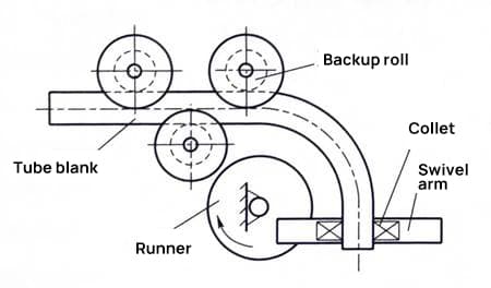
Simplified working principle of four common stretch bending forming
(2) Swivel Pull Bending
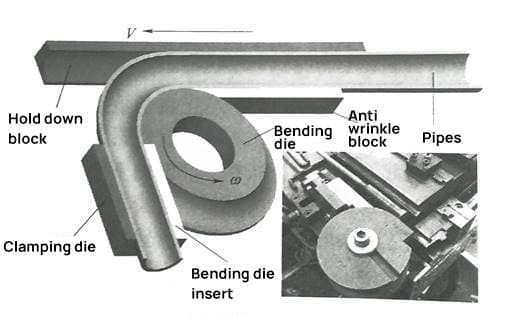
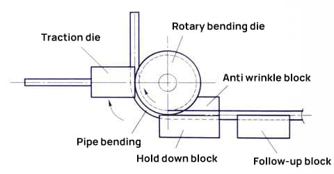
The figure below illustrates rotary pull bending, in which each working part of the bending die has a groove that matches the shape of the tube.
The length of the cross-section bend is slightly less than the semicircle of the tube blank. It is used to clamp or press the tube blank during bending.
The bending radius can be changed by replacing the rotating bending die.
The tube blank is pressed against the rotating bending die which can rotate around the axis by the pulling die and clamping block.
The pulling die rotates on the circular arc track with a fixed radius and the axis of the rotating bending die, which makes the tube blank rotate with the rotating bending die under the radial pressure and tangential friction of the block. clamping to obtain bending formation.
Due to the increase in tangential stretching deformation of the tube blank on the convex side of bending, it has the property of stretch bending.
Currently, most pipe bending equipment and CNC pipe bending machines in production operate on the principle of rotary pull bending.
CNC tube bender rotary pull bending
2. Compression bending
Compressive bending is the counterpart of tension bending, which is obtained through the joint action of additional or derived axial thrust and bending moment in pipe bending.
The additional axial thrust can reduce or neutralize the tangential stress on the convex side of the curve, thus preventing the curve wall thickness from thinning or cracking. However, increased tangential compressive stress on the concave side of the bend can cause the pipe wall to thicken or even wrinkle.
Pipe compression bending is mainly categorized into compression bending, rotary compression bending and axial force bending.
(1) Pressure bending
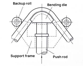
Pipe bending, as illustrated in the figure below, is similar to sheet metal V-bending and is used to bend and shape medium and small diameter elbow products with straight pipe segments.
The bending die and support roller have a working groove with the same diameter as the tube and slightly smaller than the semicircle.
The bending die, consolidated with the rod and having a specific bending radius, pushes the raw tube outward and rolls two bending shapes between the support rollers on both sides.
Replacing the bending die can change the bending radius of the tube, while the size of the two internal bending angles is determined by the expulsion stroke of the bending die.
Tube bending features high production efficiency and die adjustment is simple.
However, the disadvantage is that the bending force applied during bending is concentrated between the two support rollers. The initial contact between the tube blank and the bending die is likely to distort the offset section, affecting the quality of the bend.
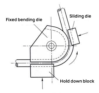
(2) Rotary compression bending
Rotary compression bending is similar in form to rotary tension bending, but the mechanism for bending the tubes is different.
As shown in the figure below, during the bending process, the sliding die or roller applies radial pressure to the tube mold while rotating around the axis of the fixed bending die, gradually forcing the straight tube mold to adhere to the groove surface of the tube. fixed mold. bending the die under tangential friction to bend and form.
Unlike rotary tensile bending, the bending deformation zone is generated between the sliding die and the fixed bending die. The surface of the convex tube blank is always subjected to the combined action of radial pressure and tangential friction, which can, to a certain extent, reduce the tangential tensile deformation of the convex tube blank.
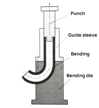
(3) Axial force impulse bending
The mold shown in the figure below consists of two halves centered on the bending plane.
Under the axial thrust of the die, the tube blank is forced to be bent and formed by pressing it into the mold cavity after passing through the guide sleeve.
The bending deformation process of the tube blank in the mold is complex. In addition to being subject to bending torque, it is also subject to axial thrust and frictional force opposite its direction of movement.
Pressure bending is different from ordinary bending in that the neutral layer of pipe wall deformation can move out of the bending, which helps to alleviate the thinning of the outer wall.
To prevent wrinkling or twisting within the elbow, the relative thickness of the pipe wall pushing the bend must be greater than 0.06.
To reduce friction, it is often necessary to lubricate the tube blank or bending mold cavity.
For thin-walled elbows, core pressure bending is generally adopted to avoid buckling and wrinkling.
3. Other common tube bending methods without mandrel
In addition to the methods mentioned above, there are also deviation bending, roll bending and others.
However, most of these methods may not meet the strict bending accuracy and quality requirements. Therefore, they are typically used to bend pipe fittings that do not require high precision in terms of shape and size.
(1) Tube bending formation
Tube bending is a common manufacturing process that can be performed manually or using a tube bending machine.
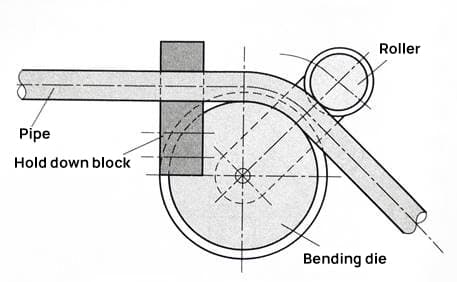
Deviation bending, as shown in the diagram below, is similar to rotary compression bending, except that rolling friction occurs between the working groove of the roller and the surface of the tube blank.
During the bending process, one end of the tube blank is clamped in the clamping head of the bending die, while the side pressure wheel presses it against the groove surface of the bending die and rotates around the bending die. The clamping head also rotates along with the tube blank.
(2) Tube roll forming
Pipe roll bending is commonly used to bend thick-walled pipes, as shown in the diagram below.
The pipe blank is placed between three or more rollers, each having a groove with an inside diameter slightly larger than the outside diameter of the pipe and a section circumference slightly smaller than the semicircle of the pipe blank.
Each roller rotates and moves in different directions, which allows the tube blank to be rolled into a specific bend shape. Multi-roll bending can increase the bending accuracy of pipes, reduce bending cross-section distortion, and improve the uniform bending deformation degree of the pipe.
Although it is mainly used to bend thick-walled pipes, it can sometimes also be used to bend thin-walled pipes.
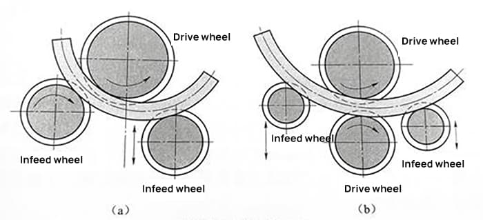
(a) Schematic diagram of asymmetric three-roll bending
(b) Schematic diagram of four-roller bending with lateral swing
Tube filling bending
Tube fill bending, also known as mandrel bending, is a common process for bending medium to large diameter thin-walled tubes.
To minimize or eliminate defects such as cross-sectional flattening, wall collapse and wrinkling during the bending process, a method called fill bending is used. This involves stuffing various mandrels or fillers into the tube blank to be bent to provide support during the bending process.
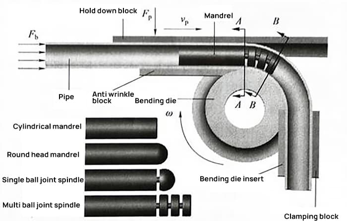
1. Chuck Bending
Mandrel bending is a bending process that provides precise control over the cross-sectional shape of elbows.
The main difference between mandrel bending and ordinary mandrel bending is that a mandrel is pre-placed inside the tube blank during the bending process.
In actual production, mandrels or mandrel rods are categorized into two types: rigid mandrels and flexible solid mandrels.
Rigid chucks include round head chucks, spoon chucks and megaphone chucks.
Flexible chucks include single-section flexible chucks and multi-section flexible chucks.
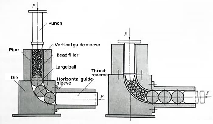
2. Solid particle filling, pressure bending formation
Solid particle filling and pressure bending forming are common processes for bending thin-walled members or elbows with small wall thickness.
Traditionally, quartz sand was used as a filler, but it was gradually replaced by resin particles or metal spheres.
Before the pressure bending process, large diameter balls, slightly smaller than the outside view of the tube blank, are placed in the bending die to prevent the bead filler from slipping out. Then the blank tube is filled with small diameter spheres.
During pressure bending, the press slider drives the pressure bending punch to extrude the bead filler into the tube mold. However, it should be noted that solid particles cannot be considered as a continuous medium and their deformation in flow under pressure cannot be approximated at a constant volume.
Furthermore, the use of hard steel balls may cause defects such as notches on the inner wall of the elbow.
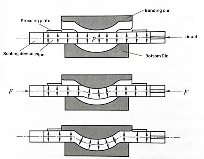
3. Liquid Filling Fold
The method of filling and bending using liquid as filler for tubes has been developed, with two relatively mature processes: hydraulic punch bending and tube punching and feeding bending.
Although liquid filling bending overcomes some of the shortcomings of solid particle filling bending, medium sealing remains a technological challenge.
4. Cure flexion with liquid filler
In the liquid filling bending process, a curable liquid is injected into the empty tube while it is in a liquid state. Once both ends are sealed, the liquid substance solidifies and becomes an integral filler that is used for bending.
Solidified filler materials may include water, rosin, low-melting alloy, and various types of resins.
Warming Fold
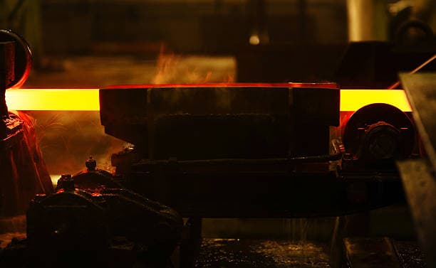
Heat bending is a traditional plastic processing method where heating is used to soften the tube blank and increase its plastic deformation capacity. This method is used when the shape of the tube components is not suitable for cold bending.
The bending process usually involves a combination of heating, bending and cooling. Commonly used methods for heating bending include general heating filling bending, general heating immersion bending, local medium frequency induction heating bending and laser bending.