There are a large number of types of foundations used in building structures. Without a doubt, we need at least one type of foundation to build a structure.
As discussed in the article How to determine the type of foundation, we can choose the most suitable type of foundation.
There are basically two types of foundations.
- Shallow foundations
- Deep foundations
So, let's discuss each type of foundation in detail.
Shallow foundations
As the name suggests, shallow foundations are built at a specific depth.
Shallow foundation is also called strip foundation.
Although the foundation is constructed at a shallow depth, a significant depth of excavation may be required for the foundation due to poor soil conditions.
Soil improvements may be carried out as recommended in the soil test report for shallow foundations. This increases the depth of the excavation many times over.
Shallow foundations can be divided into two main categories.
- Surface foundations other than mat foundations
- Mat foundations/slab foundations
Surface foundations other than mat foundations
There are many types of foundations that we can discuss in this context.
Let us briefly discuss each type with necessary information.
1. Individual foundations
It is also called an insulated foundation.
The most commonly used type of foundation for small and medium-sized buildings.
The simplest type of concrete foundation. It is very easy to build and due to its simplicity there is also less chance of design and construction errors.
Unlike other types of foundations, building individual foundations is very simple. To do this, follow the steps below.
- Assuming that the axial load is “N” (use limit), the permissible load capacity of the soil is “BC”.
- Foundation Macaws; A=N/BC
- The length/width of the foundation is √A
- Calculate the “UL” breaking load, which consists of dead load, live load, wind load, etc. Each load is multiplied by the corresponding factors.
- Calculate the maximum pressure under the foundation = UL/A
- Since we know the pressure, the bending moment can be calculated. The bending moment at the column surface is taken into account in the foundation design.
- Estimate the depth of the foundation and calculate the reinforcement.
- Check for shear and punching in the vertical line. This means that shear stresses are measured at the surface of the column or at 1.5 x effective depth. This shear range may vary from pattern to pattern. The article Punching design For more information you can contact us.
- The depth of the foundation is chosen so that the formation of shear elements is not necessary.
The example created for Eurocode Single foundation project For more information you can contact us.
2. Blended Foundations
A combination of two supports across a single foundation can be called a combined foundation. If the supports are close together, the foundation area will increase due to low load-bearing capacity, etc., which are also reasons for combining foundations.
Combined foundations differ slightly in their construction from individual foundations.
The article Combined Design Foundation represents a practical example for Eurocode 2.
3. Strip foundation connected to the column
What is a strip foundation? When should strip foundations be built?
Strip foundation is a type of combined foundation, where the two foundations are not connected to each other, but by a beam.
If the supports are on the edge or very close to the edge, they cannot be placed in the center of the foundation.
Place the column on the edge of the foundation to create an unbalanced moment that causes pressure fluctuations under the foundation.
Increased pressure near the column can cause excessive settlement in the foundation. Therefore, to minimize foundation rotation, we design a beam connecting two foundations and columns.

Building foundations is not as easy as building individual foundations. It requires more calculations and attention.
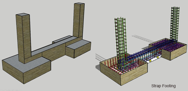
4.Belt base with counterweight
The beam serves to transfer the rotation of the foundation to the other column through shear force and bending moment. The upward reaction to the countercolumn balances the system.
Instead of a pillar, we can build or place a mass of concrete to balance the upward reaction.
The size of the block to be built depends on the maximum vertical upward reaction.

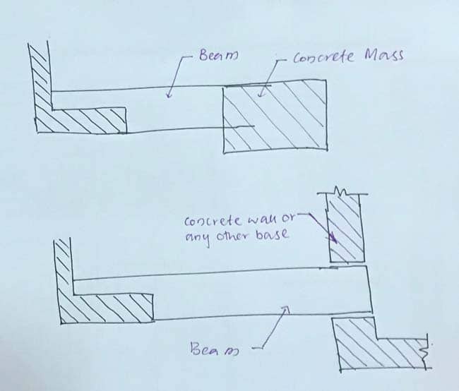
Furthermore, a brace beam can be supported by a confining body such as concrete walls, foundations, etc. as indicated in the figure above.
5. Taking out foundations
Strip foundations are erected when the distance between the pillars is small or the applied load cannot be supported by isolated or combined foundations.
The construction of a strip foundation increases the area and reduces the pressure exerted on the soil.
These types of foundations are best suited for soils with low load-bearing capacity.
There are basically two methods for designing strip foundations.
- Design as a rigid base
This method calculates the average of the loads applied by the supports along the length and takes into account the uniform pressure in the design.
- As a flexible base
Theories such as beam on elastic base are taken into consideration in the design. The variation in ground pressure under the base is taken into account. Furthermore, the construction of the foundation as support reduces different settlements.
Manual calculation is a little difficult because we have to do more calculation work.
Computer software can be used to perform the analysis. Soil can be modeled as a spring using the underground reaction method. Additionally, we can also use the line spring. So the foundation strip should be seen as a line element.
The most suitable method is to model the foundation with surface elements and the floor with spring elements.
Soil suspension or soil reaction Ks can be calculated using the following equation.
Ks = (FS) x 40 x BC
Where,
FS: Safety factor applied to the soil to calculate the allowable load capacity (we could use the value in the range of 2-3 )
BC: Permissible bearing capacity of the soil.
If we perform the analysis using software such as SAP2000, Etabs, Safe, etc. we can find the bending moments and shear forces which can be used for further designs.
6. Fundamentals of the inverted “T”
A further development of strip foundations are “inverted T” foundations. As the axial loads of the columns increase, we need to provide greater foundation thicknesses.
This is not an economical way to increase subgrade stiffness.
Therefore, beams are constructed along with the foundation to provide additional rigidity.
Thus, the beam, together with the foundation, provides stiffness in the middle of the span and supports the bending and shear forces at the supports.
Reduce foundation thickness by introducing beam and foundation designs for beam cantilever effect.
An analysis procedure similar to that discussed for strip foundations could also be used to analyze inverted-T foundations.
Mat foundations/slab foundations
A mat foundation, also known as a slab foundation, is a combined substructure that covers the entire foundation area.
These types of foundations are best suited for soils with low load-bearing capacity.

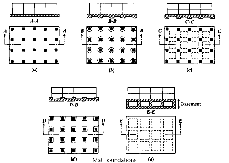
Furthermore, as the axial load increases, the area of the foundation increases. With the increase in the foundation area, we cannot create an isolated foundation base.
There are different types of treadmill bases.
- Flat plate
The flat slab foundation is a thick slab of concrete. It has uniform thickness across the entire surface. This is the most prepared type of foundation as it is easy to build compared to other types.
Due to its simplicity, it is a comparatively cheap type of foundation.
- Flat slab and thickened foundation under the pillars
Foundation subject to bending and shear forces. In general, the shear forces and bending moments at the column foundation connection are greater.
The Puncture Proof article may be worth reading this to learn more about shear range selection.
Therefore, it is necessary to increase the thickness of the foundation. Furthermore, it does not make economic sense to increase the thickness of the entire foundation. Therefore, the thickness of the foundation increases towards the bottom of the column.
Increasing the thickness downwards is somewhat difficult from a design point of view. We cannot increase the thickness upwards if the floor (upper level of the raft) is used for other purposes such as vehicle parking or similar.
- Flat slab and foundation thickened towards the top
The increase in thickness occurs as described above. If there are no restrictions or if the upper level of the slab foundation is not used for other purposes or if the free distance from the bases is sufficient for this purpose, upward facing bases can be constructed.
- Beam and slab panels
With increasing axial load on the slab foundation, it is no longer possible to proceed with a smooth foundation slab without significantly increasing the thickness.
Furthermore, increasing the thickness of the foundation slab is not an economical option. The beams connecting the supports increase the stiffness of the slab foundation and the comparatively small thickness of the flat slab can be maintained.
The beam can be projected upwards or downwards depending on the need.
Although the construction of lower beams is more difficult, we should proceed if the floor is used for a specific purpose.
- Cellular raft
A further increase in column axial loads requires an increase in beam height in a beam and slab. Furthermore, increasing the height of the beam is not such an economical option.
For this reason, a top plate is constructed that forms a cellular plate raft. Cellular plate raft has higher rigidity compared to other types of rafts.
- Raft
Generally, piles are connected to the superstructure via pile caps.
As the height of the building increases, the pile heads also become larger. If there is not a large distance between the pile heads, we connect all the pile heads and build pile plates.
If the pile is not resting on rock or anchored in the ground, pile slabs are erected to provide ground support.
In these situations, both the pile and the pile slab support the applied loads of the superstructure. It is based on the interaction between soil and foundation.


As shown in the figure above, loads are mobilized when the pile plate is laid. First, the pile begins to absorb the loads and gradually the slab pressure increases. As the pile load increases, it mobilizes its full capacity and the plate pressure increases. Then the pile and slab reach the maximum capacity corresponding to the maximum load.
The article appeared as Pile slab foundation could be forwarded for more information.
Deep foundations
Types of foundations built deeper than shallower ones fall into this category.
Most of the time we try to build buildings on shallow foundations because the construction cost is too high, quality control and assurance are difficult, the project is delayed by the time needed to complete the foundation, etc.
There are basically three types of deep foundations.
- Pile foundations
- diaphragm walls
We will discuss each activity individually.
Pile foundations
Compared to other types of foundations, this is the most commonly used method of building structures. Depending on the type of construction, we can use different types of pile foundations.
A distinction is essentially made between the following types of pile foundations:
- Bored piles cast in place
- driven pile (prefabricated piles)
- Micropiles
- Sheet pile walls
- wooden posts
The article Pile Foundations Discuss the design, construction and testing aspects of pile foundations.
diaphragm walls
Compared to other types of deep foundations, diaphragm walls represent a modern development in foundation construction technology.
It is a concrete wall built vertically downwards and anchored into the rock.
Although it is a wall, the construction process is more similar to that of cast-in-place concrete bored piles.

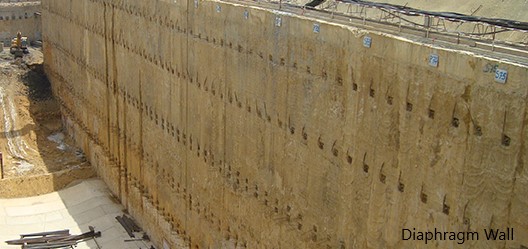
The construction of diaphragm walls offers other advantages:
- They can be used as construction elements to support loads.
- Could be used to protect soil in basements.
- Can act as a waterproof wall
- Compared to other construction methods, vibrations and noise levels are lower.
Construction of a secant pile wall is more difficult and expensive compared to diaphragm walls. Furthermore, construction also saves comparatively time.