Note: It is recommended that you follow this series of VHDL tutorials in order, starting with the first tutorial .
In the previous tutorial, VHDL Tutorial – 14, we designed two circuits using VHDL: a 1x8 demultiplexer and an 8x1 multiplexer.
In this project we will,
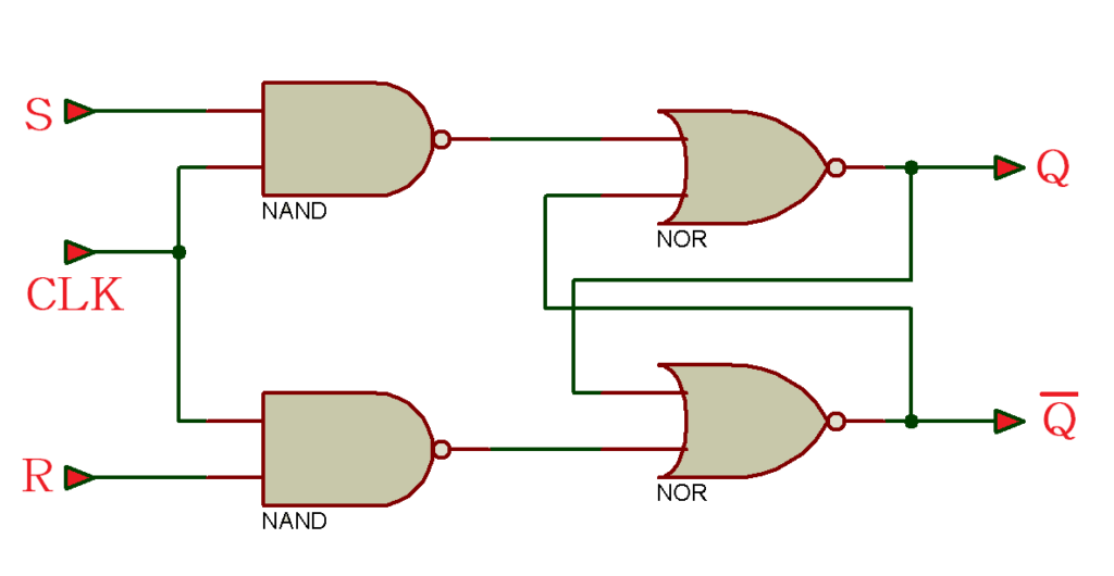
- Write a VHDL program to build a clocked SR Latch (flip-flop) circuit
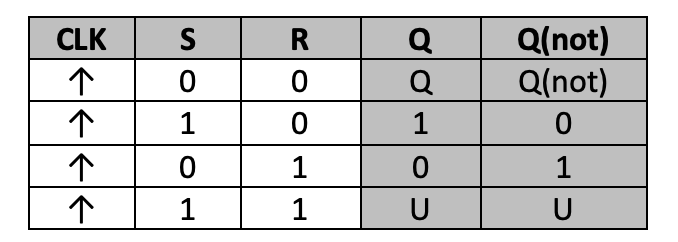
- Check the output waveform of the program (the digital circuit) with the truth table of the flip-flop circuit
A clocked SR latch circuit:
Truth table
Now let's write, compile and simulate a VHDL program. Then we will get the waveform output and check it with the given truth table.
Before you begin, be sure to review the step-by-step procedure provided in VHDL Tutorial – 3 to properly design the project as well as edit and compile the program and waveform file, including the final output.
For this tutorial, we use a behavioral modeling style to write the VHDL program that will build the flip-flop circuit. This is the preferred modeling style for sequential digital circuits.
VHDL Program
ieee library;
use ieee.std_logic_1164.all;
entity RS_FF is
port (clk,r,s: in std_logic;
Q: out std_logic;
Qnot: out std_logic);
end RS_FF;
RSFF_arch architecture of RS_FF is
signal t1,t2: std_logic;
to start
t1 <= r nor t2;
t2 <= s nor t1;
process (clk,r,s)
to start
if(clk'evento and clk='1′ ) then
if(r='0′ and s='0′) then
Q<=t1;
Qnot <= t2;
elsif(r='0′ and s='1′) then
Q<='1';
Qnot <='0′;
elsif(r='1′ and s='0′) then
Q <='0';
Qnot <='1′;
elsif(r='1′ and s='1′) then
Q <='X';
Qnot <='X';
end if;
end if;
end of the process;
end RSFF_arch;
To refresh your memory on how this works, read the first two VHDL tutorials ( 1 and 2 ) in this series.
Next, compile the above program, creating a waveform file with all the necessary inputs and outputs listed, and simulate the project. You should get the following result…
Simulation waveform

As shown in this figure, when the clock input is '1', then “s” is '1'. And when “r” is '0', the flip-flop is set – meaning the output Q is '1' and Qnot is '0'.
Be sure to check the different combinations with the truth table provided.
In the next tutorial, we will design a D flip-flop using VHDL.