Transmitting digital data through an RF module is quite common. RF 434 modules are capable of transmitting 4-bit data along with the address byte. The circuits that use RF modules for digital data transmission are simple and use HT12E encoder and HT12D decoder ICs for parallel to serial and serial to parallel data conversion respectively. In real-life situations, the source of digital data is only computers, microcomputers or digital ICs. The real world is not digital, it is analog. Like, most sensors are actually analog sensors and are capable of transmitting the analog data to digital format only when a microcomputer processes it from analog to digital format.
The most commonly used Arduino microcontrollers in hardware projects are also capable of reading analog data and representing it in digital format. Digitizing analog data into a digital format can be accomplished using Arduino's open source virtualWire library. The read analog data can be sent serially to an RF transmitter from any digital input/output pin.
This project demonstrates the reading of analog data from the LDR sensor by an Arduino board and its transmission to another Arduino board that displays the data in digitized form on an LCD screen.
Required components
| Mr. No | Required components | Amount |
|---|---|---|
| 1 | RF Rx Module (434 MHz) | 1 |
| two | RF Tx Module (434Mhz) | 1 |
| 3 | LDR | 1 |
| 4 | LCD | 1 |
| 5 | 1k pot | 1 |
| 6 | 10k resistor | 1 |
| 7 | Arduino pro mini development board | two |
| 8 | Battery – 9V | two |
| 9 | Bread Board | two |
| 10 | Connecting wires |

Figure 1: Block diagram of Arduino-based analog RF data transmitter
Circuit Connections
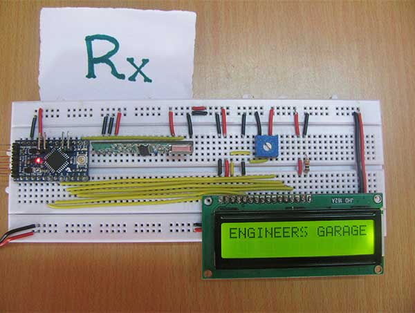
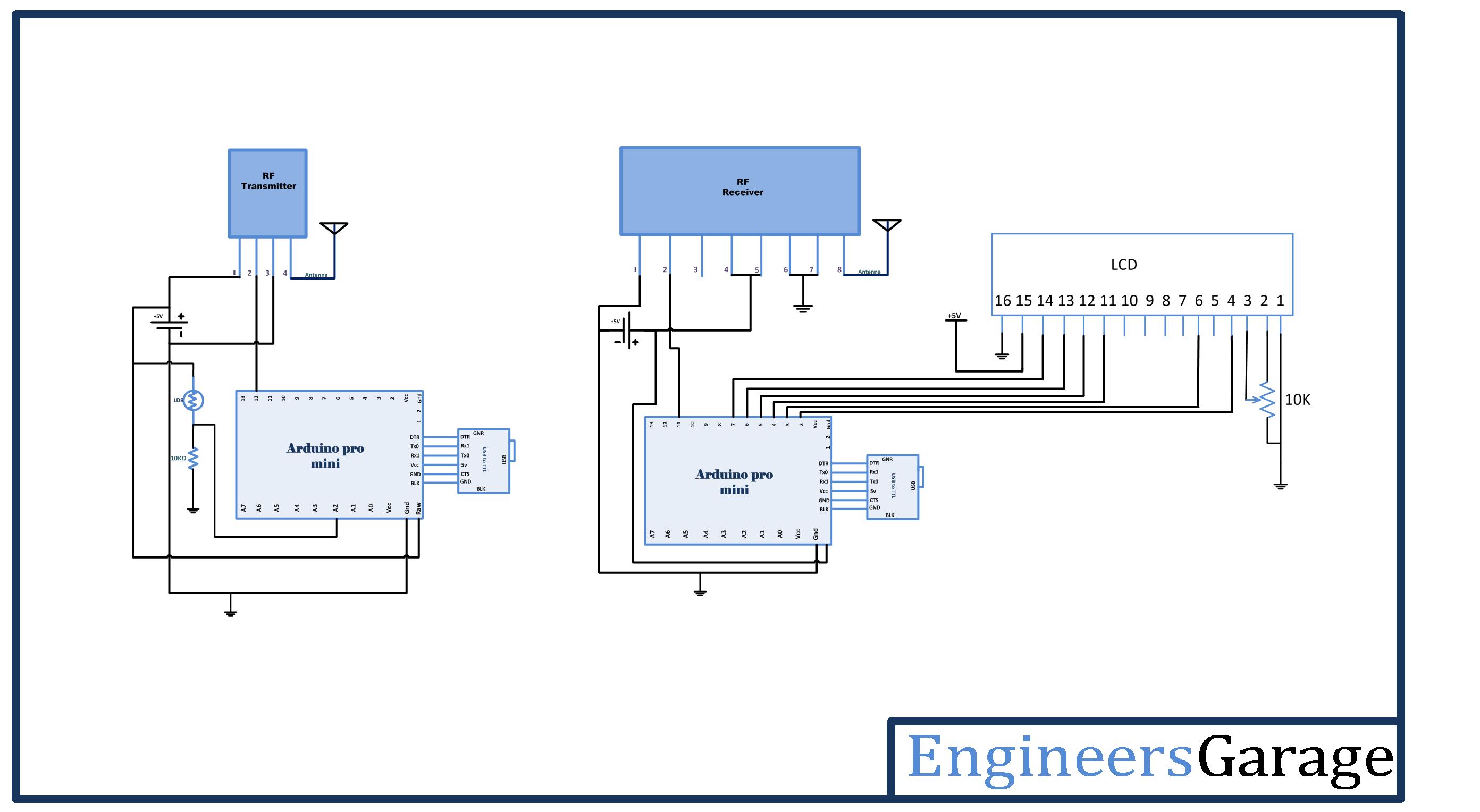
On the display side, the serially transmitted data is fetched by an RF receiver. Pin 2 of the receiver is connected to pin 11 of the second Arduino board. An LCD is connected to the Arduino board to display the received sensor reading. The 16X2 LCD display is connected to the Arduino board by connecting its data pins to pins 7 to 4 of the Arduino board. The RS and E pins of the LCD are connected to pins 3 and 2 of the Arduino ProMini, respectively. LCD RW pin is grounded.

Fig. 2: Table listing circuit connections between Arduino Uno and Character LCD
The standard code library for interfacing Arduino UNO and Arduino Pro Mini is used in the project to program the LCD with the board.

Fig. 3: Receiver-side prototype of Arduino-based analog RF data transmitter
How the circuit works
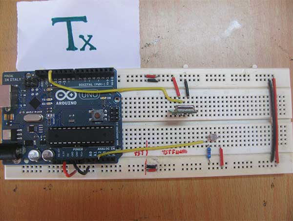
The LDR sensor works on the principle of photoconductivity. Its resistance is reduced when light falls on it, as the resistivity of the sensor is reduced when exposed to light. The LDR sensor is connected in pull-up configuration. The voltage is reduced first by the LDR and then by the output junction and pull-up resistor. When light falls on the LDR, its resistance is reduced and therefore the voltage drop across the pull-up resistor on the analog data pin is greater. Although when the LDR is covered to restrict its exposure to light, the resistance value increases so that the voltage drop across the pull-up resistor on the analog data pin is reduced. Analog reading is performed on pin A2 of the Arduino Pro Mini. This can be done on any pin from A0 to A7 on the Arduino Pro Mini.
The read analog data is stored digitally in a variable in the program code that is converted to a digitized decimal form using program logic. The digitized reading comes out in series from pin 12 of the Arduino board on the transmitter side to the RF transmitter.
The digitized reading is detected by the RF receiver and outputs in series from pin 2 of the receiver to pin 11 of the Arduino board on the receiver side. The reading is displayed on an LCD screen using functions from the lcd.h standard library in the program code. The main execution of the project is software-oriented, so the program code is the one that needs to be carefully understood.

Fig. 4: Transmitter-side prototype of Arduino-based analog RF data transmitter
Programming guide
On the transmitter side, the Arduino board must read the analog reading in the form of voltage drop across the sensor interface pin. For the same, the VirtualWire library is imported.
#include
An LED was connected to pin 13 for a visual indication of data transmission. A variable “ledPin” is declared and assigned to pin 13. The LDR sensor is connected to pin A2, then a variable “Sensor1Pin” is declared and mapped to pin A2 of the Arduino. A variable “Sensor1Data” is declared to fetch analog reading digitally and array “Sensor1CharMsg” is created for precise 3-digit decimal representation of the reading.
//LEDs
const int ledPin = 13;
//Sensors
const int Sensor1Pin = A2;
int Sensor1Data;
A setup function is called, within which the LED-interfaced pin is set to digital output and the sensor-interfaced pin is set to input mode using the pinMode function. The Arduino baud rate is set to 9600 bits per second using the Serial.begin function. The baud rate for serial output is set to 2000 bits per second using the vw_setup function of the VirtualWire library.
A loop function is called where analog data from pin A2 is read using the analogRead function and assigned to the Sensor1Data variable. The Seria1Data value is converted to decimal format representation and stored in the Sensor1CharMsg array using ito's integer to character conversion function.
empty loop
The readings stored in the variable and array are buffered serially using the Serial.print function.
The LED interface pin is set to HIGH to light the LED as an indication of data transmission. The reading stored in the Sensor1Char array is converted to unsigned characters until all four elements of the array are converted to unsigned char format. Characters are sent serially using the vw_send function and the vw_wait_tx function is used to continue transmission until all data (all four characters) are serially removed from the buffer. The LED is off to indicate that data transmission is complete.
On the receiver side, again the VirtualWire library is imported for reading analog data.
A ledPin variable is assigned to pin 13 where the data reception indicator LED is connected. A Sensor1Data variable is declared to read the data reading as integer and the Sensor1CharMsg array is created to map the decimal form of the data reading.
A configuration function is called, where the receiver-side Arduino baud rate is set to 9600 bits per second using the Serial.begin function. The pin connected to the LED is defined as digital output.
The RF transmitter and receiver module does not have a Push To Talk pin. They are inactive when no data is present to transmit or receive respectively. Therefore, vw_set_ptt_inverted(true) is used to set the push to talk polarity and request the receiver to continue receiving data after fetching the first character. The baud rate for serial input is set to 2000 bits per second using the vw_setup function. Data reception is started using the vw_rx_start function.
A loop function is called where the data in the microcontroller buffer is read and displayed on the LCD screen. An array “buf” is declared of type unsigned char to fetch received char bytes and variable “buflen” is declared to store the length of received buffer data.
The received character buffer is read using the vw_get_message function and a counter “i” is initialized. The LED interface pin is set to HIGH to indicate that data has been received, and the received character buffer is converted to character data type and stored in the Sensor1Msg array.
The last character of the array is set to Null character so that if the read buffer has less than four digits, it will not display a garbage value on the LCD screen. The elements of the Sensor1Msg array are converted to integers and stored in the Sensor1Data array. The integers of the Sensor1Data array are displayed on the LCD using the Serial.print function and the LED interface pin is set to LOW to turn off the LED as a visual indication that the data has been read and displayed successfully. The analog reading was read in the project as the voltage reading on the analog pin of the Arduino Pro Mini.
The sensor reading has not been calibrated to show any actual physical quantity, such as light intensity or luminosity, in the case of a light-based sensor. However, the actual reading of a physical quantity can be displayed through design by judging the calibration of the sensor relative to the physical quantity under measurement. The logic to convert the voltage reading into the measurement of the physical quantity under observation can be incorporated into the program logic based on sensor calibration.
Project source code
###
#include// LED's const int ledPin = 13; // Sensors const int Sensor1Pin = A2; int Sensor1Data; char Sensor1CharMsg(4); void setup { // PinModes // LED pinMode(ledPin,OUTPUT); // Sensor(s) pinMode(Sensor1Pin,INPUT); // for debugging Serial.begin(9600); // VirtualWire setup vw_setup(2000); // Bits per sec }// Read and store Sensor 1 data Sensor1Data = analogRead(Sensor1Pin); // Convert integer data to Char array directly itoa(Sensor1Data,Sensor1CharMsg,10);// DEBUG Serial.print("Sensor1 Integer: "); Serial.print(Sensor1Data); Serial.print(" Sensor1 CharMsg: "); Serial.print(Sensor1CharMsg); Serial.println(" "); delay(1000); // END DEBUGdigitalWrite(13, true); // Turn on a light to show transmitting vw_send((uint8_t *)Sensor1CharMsg, strlen(Sensor1CharMsg)); vw_wait_tx ; // Wait until the entire message is gone digitalWrite(13, false); // Turn off a light after transmission delay(200); } // END void loop... #include// LED's int ledPin = 13; // Sensors int Sensor1Data; // RF Transmission container char Sensor1CharMsg(4);void setup { Serial.begin(9600); // sets the digital pin as output pinMode(ledPin, OUTPUT); //VirtualWire // Initialize the IO and ISR // Required for DR3100 vw_set_ptt_inverted(true); // Bits per sec vw_setup(2000);// Start the receiver PLL running vw_rx_start ; } // END void setupvoid loop { uint8_t buf(VW_MAX_MESSAGE_LEN); uint8_t buflen = VW_MAX_MESSAGE_LEN; // Non-blocking if (vw_get_message(buf, &buflen)){ int i; // Turn on a light to show received good message digitalWrite(13, true); // Message with a good checksum received, dump it. for (i = 0; i < buflen; i++){ // Fill Sensor1CharMsg Char array with corresponding // chars from buffer. Sensor1CharMsg(i) = char(buf(i)); }// Null terminate the char array // This needs to be done otherwise problems will occur // when the incoming messages have fewer digits than the // one before. Sensor1CharMsg(buflen) = ''; // Convert Sensor1CharMsg Char array to integer Sensor1Data = atoi(Sensor1CharMsg);// DEBUG Serial.print("Sensor 1: "); Serial.println(Sensor1Data); // END DEBUG // Turn off light to and await next message digitalWrite(13, false); } }
###
Circuit diagrams
| Arduino Based Analog RF Data Transmitter Circuit Diagram |  |
Project video

