Summary:
In an effort to improve road safety, the Government has released a new regulation that states that if a vehicle approaches from the opposite side, it is necessary to dim its headlights so that it does not cause problems for the driver approaching from the other side. This would help avoid many accidents.Description:
Block Diagram:

Fig. 1: Block diagram of automatic car headlights
Description:
LDR sensor:
LDR stands for Light Dependent Resistor. It acts as a variable resistor whose resistance changes with the intensity of light. When the light intensity increases, the resistance offered by the sensor decreases and vice versa.
 used as a light sensor in the circuit")
Fig. 2: Typical image of light dependent resistor (LDR) used as a light sensor in the circuit
Circuits and Operation
Detection Circuit
I preferred the IRFZ44N due to the high current and good heat dissipation capacity.
Retransmission:

Fig. 3: Typical image of the relay used to switch the headlights
It has NC (normally closed) and NO (normally open) contacts. Other than that, “NC” contact is used where the headlight bright light is connected. The “NO” contact is used where the headlight dim light is connected. The reason is explained after describing the circuit diagram. CIRCUIT DIAGRAM: There are two headlights, one is dim and the other is bright. If you can't distinguish between them well, ask the workshop staff to fix this as there are different arrangements for different cars. The LDR must be exposed to light, so it must be placed in such a way that the lights of the opposite car approaching you fall on the LDR and not on the lights of your own car. Although the 30K resistor is suitable for my circuit, the exact MOSFET can be used. Due to the manufacturing process, one transistor cannot be exactly identical to another (its beta value can change). Therefore, the value of 30K cannot be guaranteed for your circuit, so make adjustments so that the transistor acts as a switch for the considered resistor values.Working:
When light falls on the LDR, its resistance decreases and therefore the bias voltage of the MOSFET increases, turning it on and therefore the relay status change occurs from NC TO NO. Since there is a weak bulb connected to NO, it lights up. Likewise, as the car passes, the light stops falling on the LDR and therefore its resistance increases, which causes a lower Vbe MOSFET voltage, thus turning off the transistor. The relay status change occurs from NO to NC and hence the bright lamp switches are turned on.

Fig. 4: Prototype relay circuit soldered on a printed circuit board for automatic control of automobile headlights

Figure 5: Image showing the wiring of the relay circuit for automatic control of the car's headlights

Fig. 6: Image showing welding of the relay circuit
Circuit diagrams
| Circuit-Diagram-Electronic-Circuit-Used-Auto-Car-Headlights | 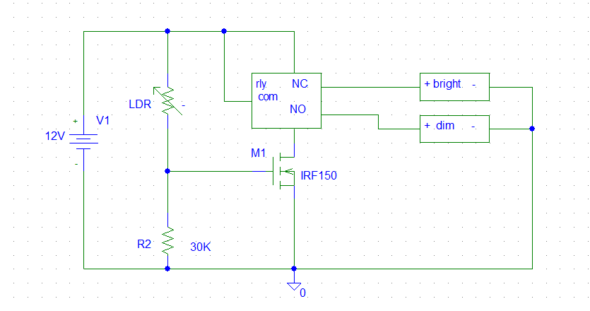 |