In one of the previous projects “Wireless Robot Controlled by Hand Gestures”, it was discussed how remote controls with switches or buttons used to control wireless robots have a disadvantage in controlling the robot due to the human response time factor who manipulates it. As a solution to the problem, the use of advanced interfaces between humans and computers, such as gesture recognition, eye movement tracking and brain waves, was suggested. Of which, hand gestures were used in the previous project to control the robot. In this tutorial, a wireless robot will be designed that will be controlled by the joystick. A joystick is not a new input device, but it provides better control over the subject. It is easier to use and handle by a human operator.
A joystick doesn't differ much from the remote control developed in the previous project. A joystick works similarly to an accelerometer sensor. Just as an accelerometer sensor outputs the change in the X-axis, Y-axis, and Z-axis dimensions of the sensor's orientation in space, similarly, a joystick outputs the change in the X-axis, Y-axis, and Z-axis dimensions of the stick mounted on it. Only changes to the X and Y axes are required to move the robot on a surface. In this project, the robot can move forward, backward, left or right based on the tilt of the joystick module. The joystick module interfaces with the AVR Atmega 32 microcontroller.
There is a 434 MHz RF module connected to the AVR circuit to connect the remote circuit to the wireless robot control circuit. In the robot circuit, simply put, an RF receiver circuit interfaces with the motor driver IC. The robot is built on two wheels and a caster body. There are two geared DC motors attached to the wheels and coupled to the L293D motor driver IC to move the robot.
An LCD is connected to the robot's remote circuit to monitor the change in axis values during control circuit testing. The robot must be calibrated for adequate sensitivity to joystick movement. The LCD module interconnected in the remote circuit flashes some initial messages at startup and then begins to display the change in the values of the X and Y axes along with the control command corresponding to them.
The control circuit of the wireless robot does not have any controller. The robot is directly controlled by digital data transmitted via the RF interface. The remote circuit has AVR Atmega 32 as a sitting microcontroller. The code that can interpret the joystick signals and pass the appropriate digital data to the robot wirelessly runs in the AVR controller. AVR code is written and compiled using AVR studio.

Fig. 1: AVR-based joystick-controlled wireless robot prototype
Required components –

Fig. 2: List of components required for AVR-based joystick-controlled wireless robot
Block diagram –
The remote circuit is constructed by bringing together the following building blocks –

Fig. 3: Transmitter-side block diagram of AVR-based joystick-controlled wireless robot

Fig. 4: Receiver-side block diagram of AVR-based joystick-controlled wireless robot
The control circuit of the wireless remote control is constructed by assembling the following building blocks –
Circuit Connections –
There are two circuits that make up the project – one is the remote circuit based on the AVR microcontroller and the other is the receiver circuit mounted on the robot. The remote circuit has the AVR Atmega 32 as a sitting microcontroller. The LCD module, ADXL335 joystick module, IC encoder and RF transmitter interface with the AVR controller on the remote circuit. The remote circuit connections are as follows –

Fig. 5: Transmitter circuit image of AVR-based joystick-controlled wireless robot
Power supply – The remote circuit requires a 5V supply to operate. The AVR Atmega 32 microcontroller, RF transmitter, IC encoder, character LCD and Joystick module operate on 5V DC. To supply power to the remote circuit, a 12V NIMH battery is used. Battery power is regulated to 5 VDC using 7805 voltage regulator IC. Pin 1 of voltage regulator IC is connected to battery anode and pin 2 is connected to ground. The regulated voltage output is taken from pin 3 of the IC. An LED along with a 10K Ω pull-up resistor is also connected between the common ground and the output pin to get a visual cue of power continuity.
AVR Atmega 32 – This is an 8-bit AVR RISC based microcontroller. It comes in a 40-pin package and has 2 KB of RAM, 32 KB of flash memory, 1 KB EEPROM, 32 general purpose input and output (GPIO) pins, 8 10-bit ADC channels, one SPI, one UART and an on-chip TWI interface. The controller has three built-in timers, of which 2 are 8-bit timers and one is a 16-bit timer. The controller operates up to a clock frequency of 16 MHz. By executing powerful instructions in a single clock cycle, the Atmega 32 achieves transfer rates approaching 1 MIPS per MHz, allowing system designers to optimize power consumption relative to processing speed. The controller is available in a 40-pin Dual Inline Package (DIP). Check out the pin diagram and pin configuration of this AVR controller here.
In this project 17 GPIO pins of the controller are used, of which 11 pins are used to interface the character LCD, 2 pins are used to interface the joystick module and 4 pins are used to connect the data pins of the IC encoder.
16X2 LCD: The 16X2 LCD display is used to monitor sensor values. It interfaces with the AVR microcontroller by connecting its data pins to the controller's B port. Character LCD data pins DB0 to DB7 interface with AVR Atmega 32 pins PB0 to PB7, respectively. The LCD's RS, RW, and E pins are connected to the AVR's PD0, PD1, and PD2 pins, respectively. Character LCD circuit connections to the AVR controller are summarized in the following table –

Fig. 6: Table listing circuit connections between Arduino Uno and Character LCD
Joystick module – A custom joystick module is used in the project. The module has five terminals for ground, VCC, X-axis analog output, Y-axis analog output, and Z-axis analog output. VCC and ground are connected to the common VCC and ground, respectively. The X-axis analog output and the Y-axis analog output of the sensor module are used and connected to pin 0 of port A and pin 1 of port A of the AVR controller, respectively.
RF Transmitter – The RF transmitter is used to transmit the control signals for controlling the motor. The RF transmitter module is a small PCB subassembly. The RF module, as the name suggests, operates on Radio Frequency. The corresponding frequency range of such modules varies between 30 kHz and 300 GHz. In this RF system, digital data is represented as variations in the amplitude of the carrier wave. This type of modulation is known as Amplitude Shift Keying (ASK). This RF module operates at a frequency of 433 MHz and uses the ASK modulation technique. The pin configuration of the transmitter module is as follows

Fig. 7: Table listing RF transmitter pin configuration
Serialized data from the encoder is received at pin 2 of the module and passed to the antenna from pin 4 of the module.
HT12E IC – The HT12E IC converts the parallel data into serial data to pass it to the RF transmitter. The IC HT12E encoder belongs to the 212 series of encoders. It is paired with 212 series decoders with the same number of addresses and data format. The HT12E is capable of encoding 12 bits, of which 8 are address bits and 4 are data bits. Thus, the encoded signal is a 12-bit serialized parallel data composed of 4-bit data to be transferred appended to the address byte.
The data pins D0, D1, D2 and D3 of the IC are connected to the PC0, PC1, PC2 and PC3 pins of the AVR controller respectively. All the address pins of the encoder IC are connected to ground, so it has an address byte of 0x00. Pin 17 of the IC is connected to pin 2 of the RF transmitter. Thus, the serialized data is passed from pin 17 of the IC to the data input pin of the RF transmitter.
The HT12E has a transmit enable pin that is active low. When a trigger signal is received at the TE pin, the programmed addresses/data are transmitted along with the header bits via an RF or infrared transmission medium. The HT12E starts a 4-word transmission cycle after receiving a transmission enable. This cycle is repeated as long as the TE is kept low. As soon as TE returns to high level, the encoder output completes its final cycle and then stops.
The robot control circuit consists of an RF receiver, an RF decoder IC and an L293D motor driver IC. The receiver circuit connections are as follows –

Fig. 8: Receiver circuit image of AVR-based joystick-controlled wireless robot
RF Receiver – The RF receiver detects the radio signal that carries engine control signals. The RF receiver module has 8 pins and the following pin configuration –

Fig. 9: Table listing RF receiver pin configuration
The RF receiver passes the serial data received by RF frequency from pin 2 to pin 16 of the decoder IC.
HT12D Decoder – The signal detected by the RF receiver is passed to the HT12D decoder. It converts serial data back to parallel data after separating data and addresses. The HT12D belongs to the 212 series of decoders and can be paired with the 212 series of encoders with the same number of addresses and data format. The HT12D is capable of decoding 12 bits, of which 8 are address bits and 4 are data bits. The 4-bit data is latch type and when passed to the output data pins it remains unchanged until new data is received.
Serial data received by the RF receiver is output in parallel from its data pins as is. The data pins of the decoder IC interface with the input pins of the L293D motor driver IC. Thus, the digital logic on the decoder data pins controls the rotation of the DC motors. All address pins of the decoder IC are connected to ground to match the address byte with 0x00 the same as the transmitter circuit.
L293D DC Motor Driver IC – The L293D is a dual H-bridge motor driver integrated circuit (IC). Motor drivers act as current amplifiers in that they receive a low current control signal and supply a higher current signal. This higher current signal is used to drive the motors. It has 16 pins with the following pin configuration:

Fig. 10: Table listing the pin configuration of the L293D motor driver IC
There are two DC motors used to make the robotic car. DC motors interface between pins 3 and 6 and pins 14 and 11 of the motor driver IC.
IC L293D controls DC motors according to the following truth tables:

Fig. 11: Truth table of L293D motor driver IC
Pins 4, 5, 13 and 12 of the L293D are grounded while pins 1, 16 and 9 are connected to 5 VDC and pin 8 is connected to 12 VDC. Pins 2, 7, 10 and 15 of the motor driver IC are connected to data pins D0, D1, D2 and D3 of the decoder IC. The DC motor connected to the right wheel is connected to pins 11 and 14, while the motor connected to the left wheel is connected to pins 3 and 6 of the motor driver IC.
Geared DC Motors – In this robot, 12V geared DC motors are attached to the wheels. Geared DC motors are available with a wide range of RPM and Torque, which allows a robot to move based on the control signal it receives from the motor driver IC.
Power supply – In the receiver circuit, the motor driver IC needs 12 VDC while the RF receiver and decoder IC needs 5 VDC for its operation. A 12V NIMH battery is used as the primary source of power in the circuit. The battery power is regulated to 5V and 12V using 7805 and 7812 ICs. Pin 1 of both voltage regulator ICs is connected to the battery anode and pin 2 of both ICs is connected to ground. The respective voltage outputs are taken from pin 3 of the respective voltage regulator ICs. An LED along with a 10K Ω pull-up resistor is also connected between the common ground and the output pin to get a visual cue of power continuity. Despite using a 12V battery, the 7812 is used to provide a regulated and stable power supply to the motor driver IC.

Fig. 12: Image showing AVR-based joystick-controlled wireless robot
How the circuit works –
As the battery is connected to the robot, the RF receiver is configured to pair with the RF transmitter and begins receiving data. On the transmitter side, first the initial messages flash on the LCD screen and the AVR microcontroller starts reading the X-axis and Y-axis data from the joystick module in the form of analog voltage. Voltage is detected by the analog input pins and converted to a digitized reading using onboard ADC channels. ADC channels are 10 bits long, so the digitized reading of the module's X-axis and Y-axis output ranges from 0 to 1023.
The digitized values are displayed on the LCD module along with the control command passed to the respective axis values. The reading is manipulated to determine whether the joystick is tilted forward, backward, left, or right. Depending on the tilt of the joystick, the controller passes the appropriate data bits to the RF encoder to drive DC motors for forward, backward, left, or right movement of the robot.
The same digital logic is reflected on the data pins of the decoder IC. The robot can be moved forward, backward, left or right by implementing the following input logic on the motor driver pins –

Fig. 13: Logic table of L293D motor driver IC for AVR robot
Check out the programming guide to learn how the AVR controller reads data from the joystick module and manipulates X and Y axis values to determine control commands. Learn from code how digital data is transmitted to the RF module to control the robot.
Programming guide –
To program Atmega 32 microcontroller, AVR Studio 4 and GCC compiler are the required software tools. To learn how AVR Studio 4 is used, see the following tutorial –
Working with AVR Studio
First of all, separate header files are imported for LCD, ADC and joystick module initialization. The lcd.h, adc.h, and joystick.h are included for programming the LCD, ADC, and joystick module, respectively.
#include
#include
#include
For the header files to work, they must be copied to the following folder – C > WinAVR-20090313 > avr > include > avr and paste the downloaded header files into the folder.
Note that in the path WinAVR-20090313, 20090313 there is a number appended to the installation folder. This number may be different on a different AVR Studio installation.

Fig. 14: Screenshot of initialization in AVR code for joystick-controlled wireless robot
The ports that are connected to the LCD and Joystick module are defined below. They are initialized to the maximum and minimum values of the x and y axes in the range where the robot is to be controlled.

Fig. 15: Screenshot of main function in AVR code for joystick-controlled wireless robot
The main function provides logic for all remote circuit operation. In this function, the pins are declared as input or output pins of the port that has already been initialized.

Fig. 16: Screenshot of infinite loop in AVR code for joystick-controlled wireless robot
The while loop inside the main function is an infinite loop, where sensor data is read and conditions are implemented to make the robot work. check out the full AVR code.
Project source code
###
//Program to #ifndef _ADC_H_ #define _ADC_H_ 1 #include#include void adc_init(void); // This function is declared to read the digital value of the ADC conversion int read_adc_channel(unsigned char channel); /*Function definitions*/ void adc_init(void) { ADCSRA=(1< ADMUX=(1< _delay_ms(1); temp=ADCL; adc_value=ADCH; adc_value=(adc_value<<8) temp; return adc_value; } #endif //************************************************ **************// //Microcontroller :ATmega32 //System Clock :1MHz //Project :joystick controlled wireless robot //Software :AVR Studio 4 //LCD Data Interfacing :8-Bit //Gives you :July 2017 //************************************************ **************// //Includes io.h header file where all the Input/Output Registers and its Bits are defined for all AVR microcontrollers #include//Defines the macro for the delay.h header file. F_CPU is the microcontroller frequency value for the delay.h header file. Default value of F_CPU in delay.h header file is 1000000(1MHz) #define F_CPU 1000000 //Includes delay.h header file which defines two functions, _delay_ms (millisecond delay) and _delay_us (microsecond delay) #include //Defines a macro for the lcd.h header File. LCD_DATA_PORT is the microcontroller PORT Register to which the data pins of the LCD are connected. Default PORT Register for data pins in lcd.h header file is PORTA #define LCD_DATA_PORT PORTB //Defines a macro for the lcd.h header File. LCD_CONT_PORT is the microcontroller PORT Register to which the control pins of the LCD are connected. Default PORT Register for control pins in lcd.h header file is PORTB* #define LCD_CONT_PORT PORTD //Defines a macro for the lcd.h header file. LCD_RS is the microcontroller Port pin to which the RS pin of the LCD is connected. Default Port pin for RS pin in lcd.h header file is PB0 #define LCD_RS PD0 //Defines a macro for the lcd.h header file. LCD_RW is the microcontroller Port pin to which the RW pin of the LCD is connected. Default Port pin for RW pin in lcd.h header file is PB1 #define LCD_RW PD1 //Defines a macro for the lcd.h header file. LCD_EN is the microcontroller Port pin to which the EN pin of the LCD is connected. Default Port pin for EN pin in lcd.h header file is PB2 #define LCD_EN PD2 //Includes lcd.h header file which defines different functions for all Alphanumeric LCD(8-Bit Interfacing Method) #include //Includes adc.h header file which defines different functions for Analog to Digital Converter. #include //Includes joystick.h header file which defines different functions for joystick #include //Defines the lower threshold for the x-axis value of joystick #define X_MIN 100 //Defines the upper threshold for the x-axis value of joystick #define X_MAX 900 //Defines the lower threshold for the y-axis value of joystick #define Y_MIN 100 //Defines the upper threshold for the y-axis value of joystick #define Y_MAX 900 int main { //All the 8 pins of PortB are declared output (data pins of LCD are connected) DDRB=0xff; //PD0, PD1 and PD2 pins of PortD are declared output (control pins of LCD are connected) DDRD=0x07; //PC0,PC1,PC2 and PC3 pins of PortC are declared output ( i/p1,i/p2,i/p3,i/p4 pins of DC Motor Driver are connected ) DDRC=0x0f; //Variable declarations int x_axis,y_axis; //ADC initialization adc_init; //LCD initialization lcd_init; //String display in 1st row of LCD lcd_string_write("EngineersGarage"); //Cursor moves to 2nd row 1st column of LCD lcd_command_write(0xc0); //String display in 2nd row of LCD lcd_string_write("EG LAB"); //Display stays for 2 seconds _delay_ms(500); _delay_ms(500); _delay_ms(500); _delay_ms(500); //Clear screen*/ lcd_command_write(0x01); //String display in 1st row of LCD lcd_string_write("Tilt your Hand:"); //Cursor moves to 2nd row 1st column of LCD lcd_command_write(0xc0); //Start of infinite loop while(1) { //Reading x-axis value of joystick x_axis=read_joystick_x_value(0); //Reading y-axis value of joystick y_axis=read_joystick_x_value(1); //Cursor moves to 2nd row 1st column of LCD lcd_command_write(0xc0); //Checking the joystick movement to move the robot in different direction if(x_axis>X_MAX) { //Robot will move forward direction PORTC=0x0A; //String display in 2nd row of LCD lcd_string_write("Moving Forward "); } else if(x_axis Y_MAX) { //Robot will move in right direction PORTC=0x08; //String display in 2nd row of LCD lcd_string_write("Moving Right "); } else if(y_axis
###
Circuit diagrams
| Circuit-Diagram-Transmitter-Side-AVR-Joystick-Controlled-Wireless-Robot | 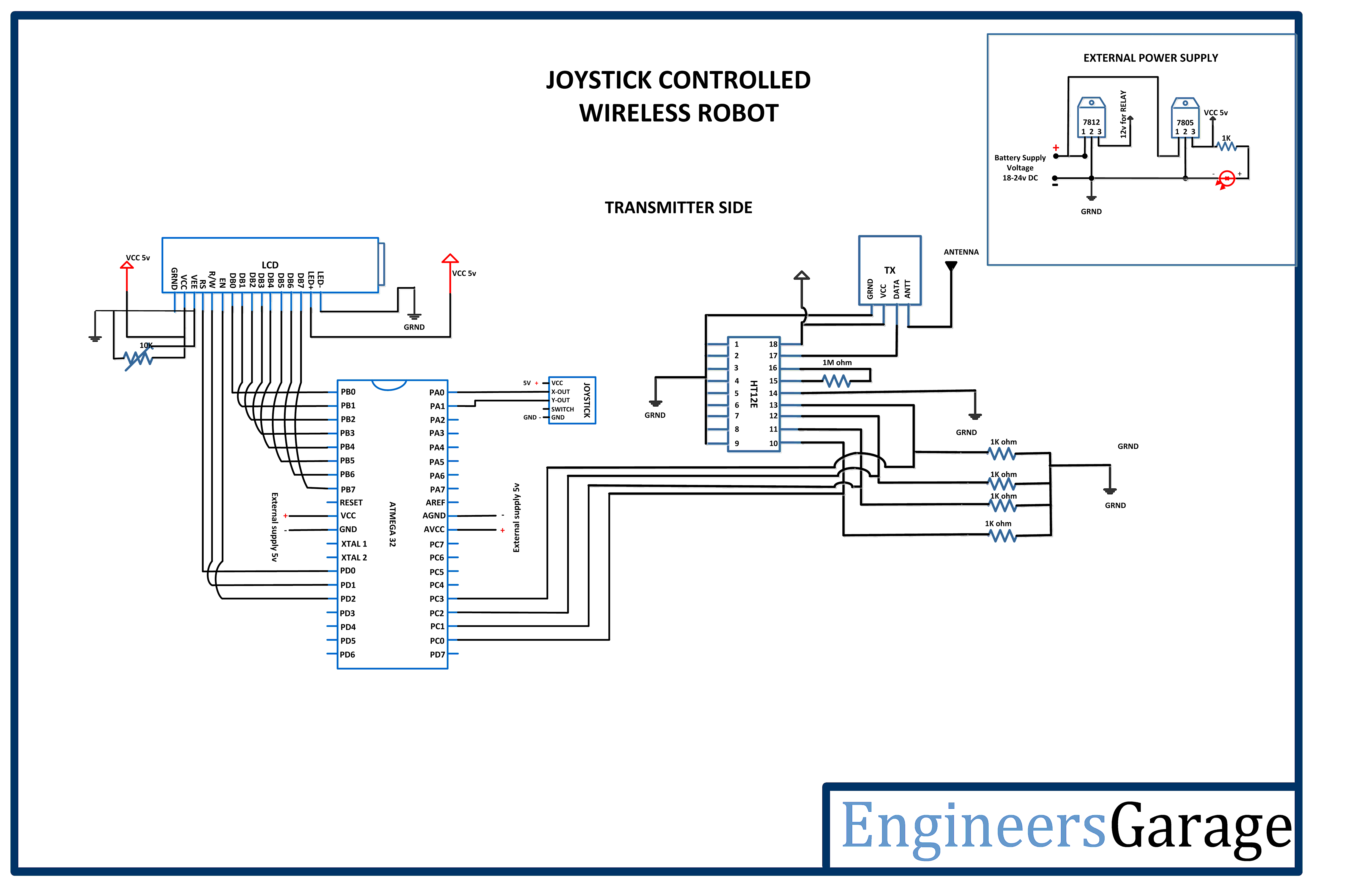 |
| Circuit-Diagram-Receiver-Side-AVR-Joystick-Controlled-Wireless-Robot | 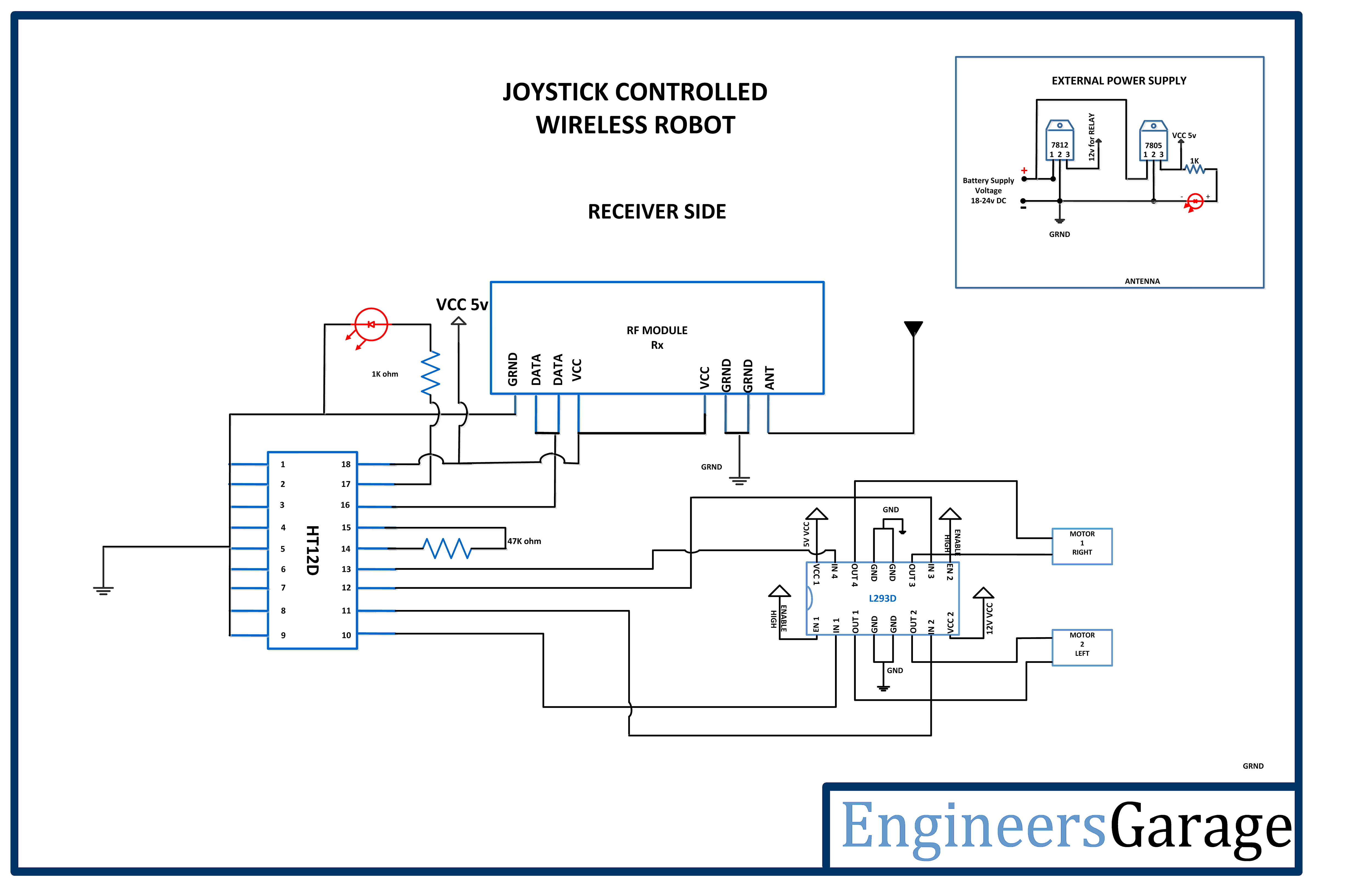 |