Introduction
Do you find it annoying when the cake you put in the freezer isn't ready on time? Maybe someone is opening the refrigerator frequently when you don't notice. Or you may have a personal closet where your things simply disappear or get lost when you are away. So how do you know when your fridge/cabinet door is opened?
Well, we have a simple solution for that. Using this technique you can check what time and also how many times it has been opened by sitting anywhere with the help of internet.
Required components
1. Arduino UNO
2. ESP 8266 Wi-Fi Module
3. SR-04 Ultrasonic Sensor (4-pin version)
4. Wires
How will we do this?
We will constantly measure the distance between the cabinet/fridge door and the ultrasonic sensor and update it on the web. Whenever the closet door was opened, the distance would show a spike.
Calculating distance using ultrasonic waves
An ultrasonic sensor measures distance using the speed of sound. Basically, the transmitter sends an ultrasonic sound wave towards an object and the receiving part receives the sound wave which is reflected from the same object. We know that the speed of sound is 330 meters per second. The sensor gives us the time it takes for the wave to reach the object and return to the receiver. Since we know the time and speed, we can easily calculate the distance from the object to the sensor.

Figure 1: Image representing the operation of the Ultrasonic Sensor
Let's say the object is at distance=' d 'meters from the sensor. The time it takes for the ultrasonic wave (shown in red) to hit the object and reflect back is T seconds and wave speed = ' S ' EM. Then,
2Xd = SXT
=> d = SXT/2
We calculate twice the distance because the wave travels from Tx to the object and then from the object to Rx. And since we know that S=330m/s we obtain,
d = 165 meters XT (where T is in seconds)
So all we need to know is how long it takes for the wave to travel from one side to the other. This time is provided by the 'Echo' pin of the SR-04 module.
ESP8266 in client mode
In our last project we saw how to use the ESP8266 module in server mode. It served as a web page for any device dialing into its IP address. Now, here the module would act as a client, which means it would connect to the internet, to a particular website and update some value on the website.
Basically we are sending the data obtained from the ultrasonic sensor to a website called thingspeak.com through the Wi-Fi module.
Algorithm:
– Test module using the “AT” command
– Set the operating mode using the command “AT+CWMODE= ”
– Connect to a Wi-Fi network using the command “AT+CWJAP=
, ”
– Connect to a website in TCP mode using the command “AT+CIPSTART= , , ”
– Using the command “AT+CIPSEND= ”, send the data you want to update on the website.
– After completion, close the connection using the “AT+CIPCLOSE” command.
About Thingspeak.com
Thingspeak.com is a website where you can upload certain data to a 'channel' that you have created and you can also see the same data in the form of a graph and that too with real-time updating. When you create an account and channel, you are given a code which is also known as 'Key' which would be used to upload the date to a specific channel.
Procedure:
1. Go to www.thingspeak.com and sign up for a free account.
2. On the registration page, don't forget to select the correct time zone. The time zone will allow the uploaded data to get a timestamp.
3. Once the account is created, you will have the option to create a channel. Click on it and leave all entries as default.

Figure 2: Screenshot of API key generation on Thingspeak server
4. Now, navigate to the ‘API’ tab and note down the “API key”
5. To test the channel you just created, type the following into your browser's address bar:
Replace for what you obtained in 4th stage .
And then press Enter. You should see a blank page with just '1' written on it.
6. Now go back to the channel page and navigate to the 'Private View' tab and you will see something like this:

Figure 3: Screenshot of channel statistics displayed on Thingspeak server
Code Explanation
Arduino basically collects data from the ultrasonic sensor, calculates the distance and uses the Wi-Fi module to update it on the thingspeak.com channel. Here are the steps to follow:
– Start serial connection with baud rate 9600. Send NO and check if OK is received. This is to ensure the presence of the module.
– Place the module in Station mode using the command AT+CWMODE=1
– Connect the module to your home network using the command AT+CWJAP=”HOME NETWORK NAME”,”PASSWORD”
– Check if the module responded OK . If yes, proceed
– Enter infinite loop
– Assign the 16th pin (which is connected to the TRIGGER & ECHO pin of the sensor) as output and set it to LOW. Wait 2 microseconds
– Set the pin to HIGH, wait 5 microseconds and again set it to LOW (Basically creating a pulse lasting 5 microseconds)
– Now assign the same pin to INPUT mode and read the duration of the pulse coming from the ECHO pin of the sensor
– Use duration to calculate distance using the microsecondsToCentimeters function. Convert the obtained value into a string type and store it in a 'cmstr' variable
– If the value changes (i.e. when the locker is opened), pass the cmstr to the updateDist function
– Connect to thingspeak.com in TCP mode using the command, AT+CIPSTART=”TCP”,”184.106.153.149”,80
– Post the distance value using the
AT+CIPSEND= function
followed by
GET /update?key= &field1=cmstr
– Close the connection using AT+CYPCLOSE
Arrangement
1. Connect the parts according to the circuit diagram.
2. Place it inside a closet so that the sensor is at least 4 cm away from the door.
3. Connect a power supply to the circuit (battery A) and within a minute you should see the output on your thingspeak.com channel.

Figure 4: Circuit prototype based on Arduino Wi-Fi modem and ESP8266 used for data logging

Figure 5: Image showing ultrasonic sensor connected to Arduino Uno
Here are some results I got:

Figure 6: Screenshot of locker statistics displayed on Thingspeak server
As you can see, when I opened it and took the time to configure the system there correctly, it already started sending data because there was a difference in distance from the closet door.
After that, around 12pm, it stopped sending data because the cabinet was closed and so there was no change in the distance between the sensor and the door for a while. And then, at about 12:52, when I open the door, it notices the change in distance and starts sending data again.
Problems solution
If the live update is not showing on the channel:
– Check and make sure your internet and Wi-Fi connection is working well.
– Check that you have provided the correct network name and password in the code.
– Check that you have substituted the correct API KEY in the code
If the update is occurring but is shown as zero:
– Make sure the ultrasonic sensor is working and the connections are tight.
Project source code
int pingPin = 16; // A2 - Connected to both Trig & ECHO Pins of the Sensorunsigned int cm_old=0;
void setup { Serial.begin(9600); Serial.println("AT"); delay(5000); if(Serial.find("OK")){ connectWiFi ; }} void loop { long duration,cm; // The PING))) is triggered by a HIGH pulse of 2 or more microseconds. // Give a short LOW pulse beforehand to ensure a clean HIGH pulse: pinMode(pingPin, OUTPUT); digitalWrite(pingPin, LOW); delayMicroseconds(2); digitalWrite(pingPin, HIGH); // Sending a High Pulse on the Trig Pin of the Sensor delayMicroseconds(5); digitalWrite(pingPin, LOW); // The same pin is used to read the signal from the PING))): a HIGH // pulse whose duration is the time (in microseconds) from the sending // of the ping to the reception of its echo off of an object . pinMode(pingPin, INPUT); duration = pulseIn(pingPin, HIGH); // convert the time into a distance cm = microsecondsToCentimeters(duration); String cmstr = String(cm); if(cm!=cm_old) updateDist(cmstr); delay(2000); cm_old=cm;} void updateDist(String cmstr){ String cmd = "AT+CIPSTART="TCP",""; cmd += "184.106.153.149"; cmd += "",80"; Serial.println(cmd); delay(2000); if(Serial.find("Error")){ return; } cmd = "GET /update?key=
&field1="; //edit the key and copy paste with your own one cmd += cmstr; cmd += "rn"; Serial.print("AT+CIPSEND="); Serial.println(cmd.length ); if(Serial.find(">")){ Serial.print(cmd); }else{ Serial.println("AT+CYPCLOSE"); }} boolean connectWiFi { Serial.println("AT+CWMODE=1"); delay(2000); String cmd="AT+CWJAP=""; cmd+="
"; cmd+="",""; cmd+="
"; cmd+="""; Serial.println(cmd); delay(5000); if(Serial.find("OK")){ return true; }else{ return false; }} long microsecondsToCentimeters(long microseconds){ // The speed of sound is 340 m/s or 29 microseconds per centimeter. // The ping travels out and back, so to find the distance of the // object we take half of the distance traveled.
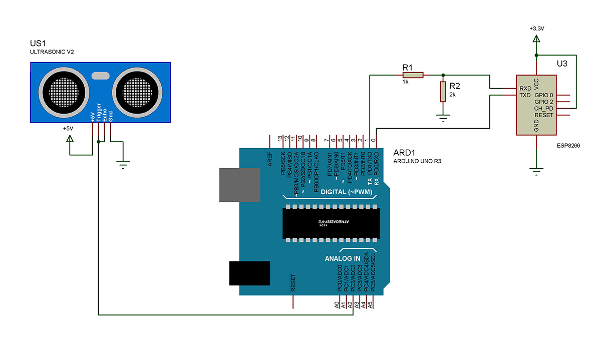
Circuit diagrams
| Circuit Diagram-Arduino-ESP8266-Wi-Fi Modem Based Data Logger Prototype |
 |