The article discusses the design of a servo motor angle controller using IC NE555. The servo motor used here for an experiment is an 11-gram micro servo motor with the following specifications.
- Rotation range 160 °
- Operating voltage 8 – 6 V
- Operating speed 500 degrees/sec at 4.8 V or 600 degrees/sec at 6 V
- Stopping torque 8 KG/CM OR 2.4 KG/CM
- Pulse width 550 us (0 o ) to 2.2 ms (160 o )
- Pulse repetition frequency (PRF) 50 Hz
The servo motor always has three terminals, one for +Ve voltage, another for –Ve voltage and the third for PWM input signal. Additionally, these three terminals are color-coded. On most motors, the red wire is for +Ve voltage input, the brown or orange wire is for –Ve voltage input, and the yellow or green wire is for PWM signal input.
The motor is powered through +Ve and –Ve wires connecting the +Ve wire with 5 to 6 V and the –Ve wire with ground. The PWM input is the actual signal that turns the motor at the exact angle. As the input pulse width varies from 500 us to 2,200 us (2.2 ms), the motor rotates from 0 o to 160 o . Furthermore, the pulse must be applied at a rate of 50 Hz, i.e. every 20 ms. As the pulse width increases continuously from 500 us to 2200 us, the motor angle increases from 0 o to 160 o and vice versa.
But as we know, IC NE555 is also widely used to generate PWM signals. Therefore, to accurately control the angle of the servo motor and rotate it at an exact angle, it is necessary to apply an accurate PWM signal, which is possible with a microcontroller. Here we illustrate how a simple servo motor angle controller can be built using IC NE555.
The IC NE555 must be configured in astable mode to generate continuous pulses, and also, its ON time must be significantly shorter compared to the OFF time. See the figure below to understand better.
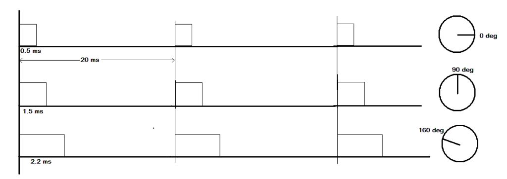
To generate such a waveform, we need the following astable configuration of IC NE555.
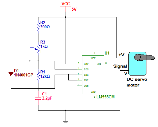
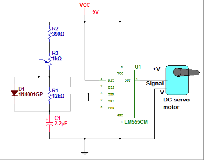
Circuit Diagram
The figure shows that IC NE555 is connected in astable mode with resistors R1, R2 and capacitor C1. There is an addition of a diode connected to R1 between terminals 7 and 6, bypassing R1 during charging of C1. The output of the chip is connected to the PWM signal input of the servo motor. The circuit receives a 5 V power supply.
Circuit design
In this circuit, the value of R1 and C1 is fixed, but the value of R2 must be variable to vary the pulse width. Therefore, to design the circuit to generate the required PWM wave, we have to find out the values of R1, R2 and C1. So let's start.
Ttotal = TON -TOFF
TOFF = Ttotal -TON
= 20 – 2.2
= 17.8
≈ 18ms
Now the equation for Toff is
TOFF = 0.69×R1×C1
Let's assume C1 as 2.2 uF. Replacing values
18×10-3 = 0.69×R1×2.2×10-6
This will give us R1 as
R1 = 11.85 KΩ
So, consider R1 as 12 KΩ. This gives us two values for circuit design
R1 = 12 KΩ and C1 = 2.2 uF
The minimum activation time is 550 nodes. It is minimum when R2 is minimum. The ON time equation is the same
TON = 0.69×R2min×C1
We know the values of TON and C1, so,
550×10-6 = 0.69×R2min×2.2×10-6
This gives R2min as R2min = 362Ω
The closest real value of R2 is 390 Ω. Therefore, R2 can be 390 Ω.
Now go to the maximum activation time which is 2200 nodes. Obviously it will be when R2 is maximum.
So, TONS = 0.69×R2max×C12200×10-6 = 0.69×R2max×2.2×10-6
This gives R2max as
R2max = 1450Ω = 1.4K ≈ 1K + 390Ω
Therefore, if we choose R2 as a fixed resistance of 390 Ω and a potentiometer of 1 K Ω, the circuit design can be perfect.
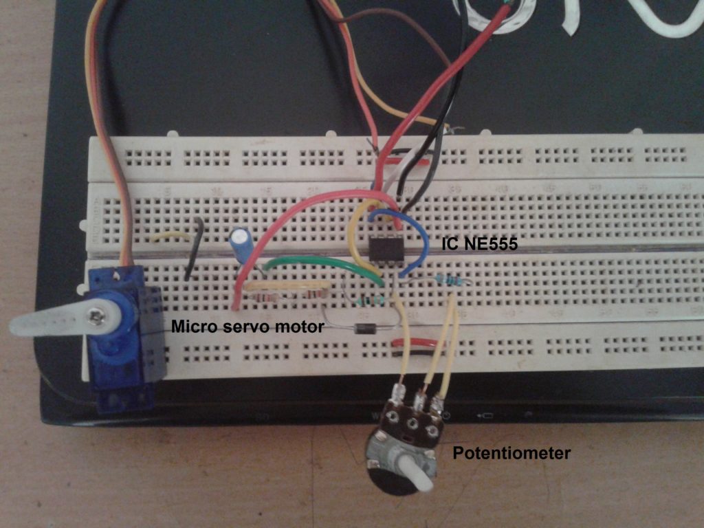
Here is the snap of the circuit built on the breadboard
Circuit operation
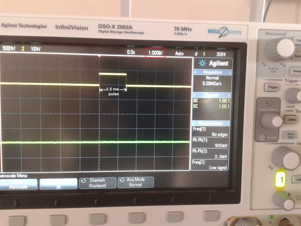
When the circuit receives a 5V supply, it generates a PWM wave at 50 Hz. When this wave is given to the servo motor, it will rotate at a specific angle. As the pulse width increases, the motor angle increases and vice versa. Here are some of the snapshots of the circuit output in DSO.

project youtube video link