DC motors are commonly used in electronics and electrical projects. It can be a line-following robot, a remote-controlled car, electronic shutters and doors, digital locks, drones and helicopters, etc.; DC motors are used in a variety of applications. Many of these applications require remote control of DC motor operations. Here, controlling the engine refers to turning the engine on or off, changing its speed, and changing the direction of its rotation. For example, a remotely controlled car may require it to start or stop, increase or decrease acceleration, or move forward or backward by controlling the above-mentioned factors of the DC motors attached to its wheels.
This project is a simple demonstration of remotely controlling a DC motor, turning it on or off and changing the direction of its rotation. The concept illustrated in the project can be used in various applications where a microcontroller may or may not be in use. Any other complex project using a microcontroller can utilize this concept by changing the receiver section of this project where the DC motor circuit directly connected to the RF receiver here can also be connected through a microcontroller.

Fig. 1: RF DC motor controller prototype
The RF module used in the project is the 434 MHz module. It transmits data at a transmission rate of 1 Kbps to 10 Kbps and can have an operational range of up to 300 meters. Learn about basic RF transmitter and receiver setup. The operating range can be extended by using a standard size antenna and increasing the transmit power of the antenna. Learn more about increasing the operating range of the RF module.
The RF module can transmit 4-bit data at once. A set of 2 bits is required as a control signal for remote operation of a single DC motor. The project shows controlling two 12V 3000RPM DC motors in the receiver section using 4-bit control signal. IC L293D (which can control maximum two DC motors) is used in the circuit.
Required components
| Mr. No. | Component name | Mandatory |
|---|---|---|
| 1 | RF TX Module (434 Mhz) | 1 |
| two | RF RX Module (434 Mhz) | 1 |
| 3 | HT12E | 1 |
| 4 | HT12D | 1 |
| 5 | LED | 1 |
| 6 | Resistor – 1KΩ (a quarter of a watt) | 8 |
| 7 | Resistor – 1MΩ (a quarter of a watt) | 1 |
| 8 | Resistor – 50KΩ (a quarter of a watt) | 1 |
| 9 | push button | 4 |
| 10 | DC motor | two |
| 11 | Battery – 9V | 1 |
| 12 | Battery – 12V | 1 |
| 13 | L293D | 1 |
| 14 | Optocoupler (MCT12E827Q) | 4 |
| 15 | Test board | two |
| 16 | 8×1 DIP switches | two |
| 17 | 8×1@1K resistor network | two |
| 18 | Connecting Wires | – |
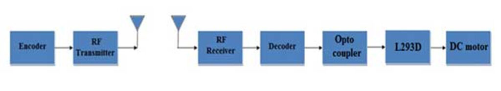
Fig. 2: RF DC Motor Controller Block Diagram
Circuit Connections
The circuit has two sections – transmitter and receiver. The transmitter section is the basic configuration of the RF transmitter, connecting the RF transmitter to an antenna and an HT12E encoder IC. The transmitter address byte is set to 0x00 by grounding all address pins, and pin 14 is also connected to ground to allow uninterrupted transmission. The push-to-on switches are connected to the data pins of the IC encoder which are connected to VCC on another terminal. By default, the encoder data pins are connected to ground, but when pressing a switch, the respective pin gets a HIGH input.
On the receiver side, the RF receiver is configured according to its basic configuration as dictated by the RF receiver and HT12D decoder IC datasheets. The IC decoder address byte is set to 0x00 to match the RF transmitter address byte.

Fig. 3: RF DC motor controller transmitter side prototype
Data bits D0 to D3 of the HT12D decoder IC are connected to the L293D motor driver controller. The data bits cannot be directly interfaced with the L293D IC. DC motors operate from a 12 Vdc high current source, while the RF receiver circuit operates from a 5 V source. A backcurrent from the DC motor circuit can damage the data pins of the decoder IC. Therefore, the data pins are first connected to optocouplers, which interrupt the return current. The optocoupler is a kind of optical isolator or optical relay. The optocoupler has a built-in IR diode at one end and a phototransistor at the other end. When current flows through the IR diode, it triggers a current in the phototransistor according to its configuration. The 4N35 optocouplers used in the circuit have six pins with the following pin configuration –:
| PIN | Function | Name |
|---|---|---|
| 1 | IR diode anode | Anode |
| two | IR diode cathode | Cathode |
| 3 | Not connected | NC |
| 4 | Phototransistor Emitter | Issuer |
| 5 | Phototransistor Base | Base |
| 6 | Phototransistor Collector | Collector |

Fig. 4: 4N25 optocoupler pin diagram
The data pins of the decoder IC are connected to the anode pin of the optocouplers and the cathode pin of the optocouplers is grounded. The collector of the optocouplers receives VCC and the output current for the L293D IC pins is drawn from the emitter pin of the optocouplers. An optocoupler is used for each data pin of the decoder IC. The respective statuses of the data pins are reflected as on the emitter pins of the optocouplers.
The L293D is the motor control driver IC. It has 16 pins with the following pin configuration:
| PIN NO. | FUNCTION | NAME |
|---|---|---|
| 1 | Enable input pins 1 and 2 of Motor 1 | Enable 1.2 |
| two | Input 1 for Motor 1 | Entry 1 |
| 3 | Output 1 for Motor 1 | Exit 1 |
| 4 | Floor | Floor |
| 5 | Floor | Floor |
| 6 | Output 2 for Motor 1 | Exit 2 |
| 7 | Input 2 for Motor 1 | Entry 2 |
| 8 | Supply voltage for Motor 1 and 2 | VS |
| 9 | Enable input pins 1 and 2 of motor 2 | Enable 3.4 |
| 10 | Input 1 for Motor 2 | Entry 3 |
| 11 | Output 1 for Motor 2 | Exit 3 |
| 12 | Floor | Floor |
| 13 | Floor | Floor |
| 14 | Output 2 for Motor 2 | Exit 4 |
| 15 | Input 2 for Motor 2 | Entry 4 |
| 16 | Logic supply voltage | VSS |
The collector pin of the optocouplers interfaced with D0 and D1 are connected to input 1 and input 2 of IC L293D, respectively. The motor to be controlled by bits D0 and D1 is connected between the Output 1 and Output 2 pins of the L293D. The collector pin of optocouplers interfaced with D2 and D3 is connected to input 3 and input 4 of IC L293D respectively. The motor to be controlled by bits D2 and D3 is connected between the Output 3 and Output 4 pins of the L293D. A 5V supply is supplied to the VSS pin and a 12V supply from another battery is supplied to the VS pin of the IC. Pins 4, 5, 12 and 13 are connected to ground.
How the circuit works
On the transmitter side, push-to-on switches are used to change the status of the encoder data bits. Pressing the switch sets the respective data bit HIGH, which otherwise by default remains LOW. Transmission is uninterrupted and by default 0x0 is transmitted.
On the receiver side, data bits are received from the data pins of the decoder IC. On successful transmission of the control nibble, the respective decoder data bit has the same status as the respective IC encoder data bit, i.e., if D0 of the IC encoder is switched to HIGH status, D0 of the IC decoder also will become HIGH. When a data bit from the decoder IC is HIGH, current flows through the anode to the cathode of the optocoupler as the anode is connected to the data pin and the cathode is grounded. This turns on the IR LED and activates the phototransistor. The base pin of the optocouplers is not connected. The collector pins are connected to VCC and the emitter pins go out to the L293D pins. Thus, the phototransistor works like a diode connected between the collector and the emitter. When receiving infrared signals due to the HIGH signal on a data pin, the collector-emitter junction is forward biased and a HIGH signal is output to the respective L293D pin.
The logic input pins of the L293D are therefore interconnected to the data pins of the decoder IC as follows:
| IC DECODER DATA PIN | PIN L293D |
|---|---|
| D0 | Entry 4 |
| D1 | Entry 3 |
| D2 | Entry 1 |
| D3 | Entry 2 |
The L293D IC controls DC motors according to the following truth tables:
| PIN1/ENABLE INPUTS 1 AND 2 | PIN 2/INPUT 1 | PIN 7/INPUT 2 | Motor 1 (connected between PIN 3 and 6) Function |
|---|---|---|---|
| LOW | N/A | N/A | The engine stops |
| HIGH | HIGH | HIGH | The engine stops |
| HIGH | LOW | LOW | The engine stops |
| HIGH | HIGH | LOW | Motor rotates counterclockwise |
| HIGH | LOW | HIGH | Motor rotates clockwise |
| PIN 9/ENABLE INPUTS 3 AND 4 | PIN 10/INPUT 3 | PIN 15/INPUT 4 | Motor 2 (Connected between PIN 11 and 14) Function |
|---|---|---|---|
| LOW | N/A | N/A | Engine stops |
| HIGH | HIGH | HIGH | The engine stops |
| HIGH | LOW | LOW | Engine stops |
| HIGH | HIGH | LOW | Motor rotates counterclockwise |
| HIGH | LOW | HIGH | Motor rotates clockwise |
Motor 1 is connected between pins 3 (output 1) and 6 (output 2) of IC L293D. While motor two is connected between pins 11 (output 3) and 15 (output 4) of IC L293D. The motors remain stopped until the enable pins remain LOW or the enable pins receive HIGH, but both input pins corresponding to the motor are HIGH or LOW. In the circuit, enable pins 1 and 9 default to HIGH and the default nibble transmitted in RF is 0x0, the LOW signal remains for the L293D input pins. Therefore, both engines remain in stop condition by default.

Fig. 5: RF DC motor controller receiver side prototype
To control motor 1, bits D3 and D2 of the transmit signal need to be changed. When pressing the switch connected to pin D3 of the encoder, 0x8 is transmitted. This in turn changes the status of input pin 2 of the L293D to HIGH, while inputs 1, 3 and 4 remain LOW. Thus, motor 1 rotates clockwise according to the truth table of L293D. When pressing the switch connected to pin D2 of the encoder, 0x4 is transmitted. This in turn changes the status of input pin 1 of the L293D to HIGH, while inputs 2, 3 and 4 remain LOW. Thus, motor 1 rotates counterclockwise according to the L293D truth table. Operations on engine 1 are summarized below:
| D3 | D2 | D1 AND D0 | Transmitted data | L293D INPUT 1 | L293D 2 input | Engine 1 Function |
|---|---|---|---|---|---|---|
| 0 | 0 | 0 | 0x0 | LOW | LOW | Engine stops (default) |
| 1 | 0 | 0 | 0X8 | LOW | HIGH | Motor rotates clockwise |
| 0 | 1 | 0 | 0X4 | HIGH | LOW | The motor rotates counterclockwise |
To control motor 2, bits D1 and D0 of the transmit signal need to be changed. When pressing the switch connected to the D1 pin of the encoder, 0x2 is transmitted. This in turn changes the status of input pin 3 of the L293D to HIGH, while inputs 1, 2 and 4 remain LOW. Thus, motor 2 rotates counterclockwise according to the L293D truth table. When pressing the switch connected to the D0 pin of the encoder, 0x1 is transmitted. This in turn changes the status of input pin 4 of the L293D to HIGH, while inputs 1, 2 and 3 remain LOW. Thus, motor 2 rotates clockwise according to the L293D truth table. The operations on engine 2 are summarized below – :
| D0 | D1 | D2 AND D3 | transmitted data | L293D 3 input | L293D 4 input | Engine function 2 |
|---|---|---|---|---|---|---|
| 0 | 0 | 0 | 0x0 | LOW | LOW | Engine stops (default) |
| 0 | 1 | 0 | 0X2 | HIGH | LOW | The motor rotates counterclockwise |
| 1 | 0 | 0 | 0X1 | LOW | HIGH | Motor rotates clockwise |
Circuit diagrams
| Circuit Diagram-RF-DC-Motor-Controller | 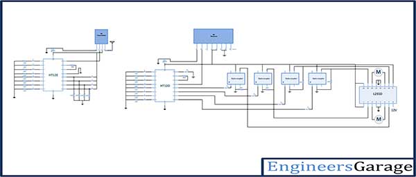 |