Stepper motors, as the name implies, move in steps. They are popular in the industry due to their ability to rotate their shaft in a precise location and produce high torque at low angular movements. It is also possible to control the speed and angle of the stepper motor precisely without the need for a feedback mechanism. Although they consume a lot of energy and their software settings are not easy to understand, once learned deeply and properly, all stereotypes about them will disappear. Stepper motors are DC motors that step and move their axis when digital pulses are supplied through their pins. Stepper motors are used in operations that require precision, such as robotic arms, 3D printers, scanners, disk rotators, and CNC machines.
Stepper motors are brushless DC motors. They have coils and permanent magnets that rotate the shaft. Generally, there are two types of stepper motors categorized into their unipolar and bipolar coil configurations. Unipolar motors have a common signal wire whose signal remains fixed at all times. Bipolar motors are independent of the common wire. I'm not going to delve into the difference between stepper motors. I just wrote above the main difference between the two stepper motors.
Stepper motors are brushless DC motors. They have coils and permanent magnets that rotate the shaft. Generally, there are two types of stepper motors categorized into their unipolar and bipolar coil configurations. Unipolar motors have a common signal wire whose signal remains fixed at all times. Bipolar motors are independent of the common wire. I'm not going to delve into the difference between stepper motors. I just wrote above the main difference between the two stepper motors.
Main project
I will interface the stepper motor with the stm32 microcontroller. My main task is to teach how to interface, program and control the stepper motor with the stm32f103 microcontroller using the stm32cubemx code configurator.
Project hardware
- NEMA 17 stepper motor
- Stm32f103c8t6 Microcontroller
- A4988 stepper motor driver
stepper motor
For this project I will use bipolar stepper motor. The name of the motor is NEMA 17. It is commonly used in 3D printers and popular among DIY circuit makers. It is a 4-wire two-phase stepper motor. Draws 1 amp to 1.5 amps of current. Voltage requirements are a minimum of 2.4 volts. The step angle is 1.8 degrees. For a full 360 degree rotation (360/1.8=200) 200 steps are required.
A4988 Stepper Motor Driver
Stepper motors draw 1 amp of current during normal operation. Therefore, we need a power supply that can provide 1 amp of direct current. The old technique is to build an H-bridge circuit using transistors or mosfets that can supply sufficient amount of power and drive motors easily. Making an H-bridge circuit is time-consuming and requires a lot of effort. Fortunately, nowadays there are pre-assembled H-bridge drivers available on the market, which are not only cheap but also very easy to control. So I decided to use a pre-assembled H-bridge circuit in this project. The A4988 bipolar stepper motor driver is best suited for our project. The A4988 can deliver 1 to 2 amps of direct current at voltages from 8 to 35 volts. It requires 3 to 5 volts for its operation. The pinout and equivalent circuit of the product are below.
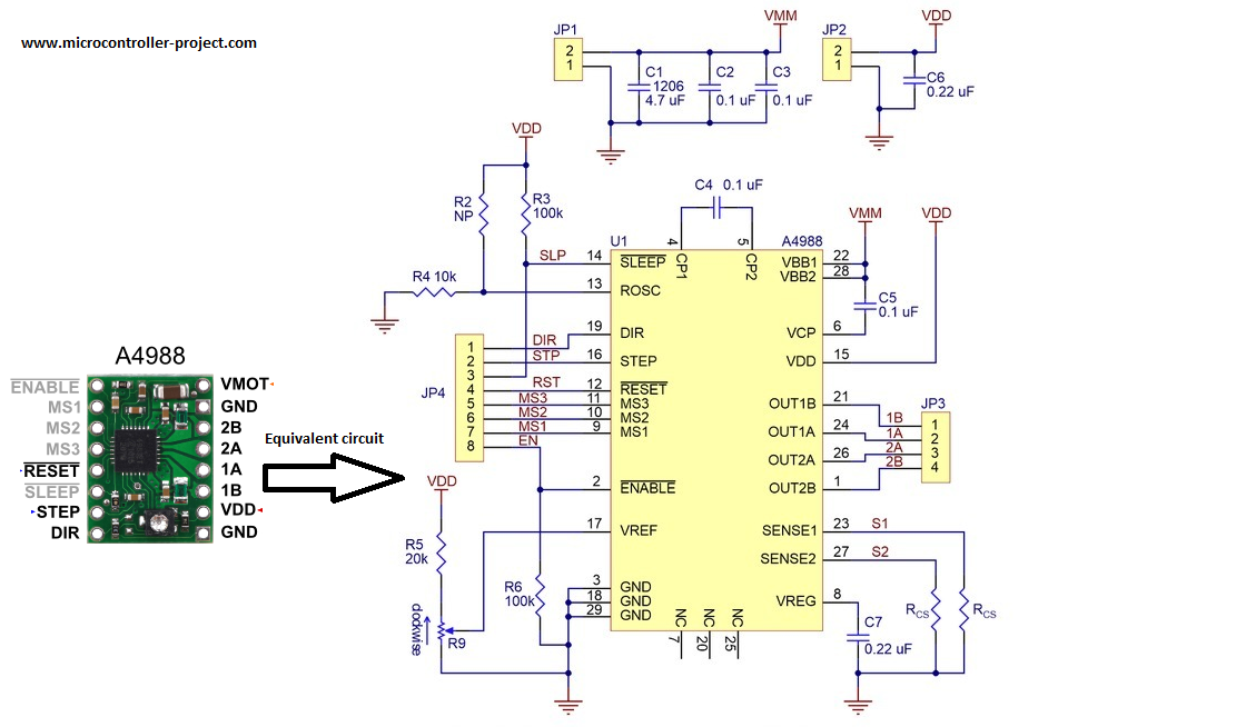
A4988 Stepper Motor Driver Equivalent Circuit
Apply 3 to 5 volts to the VDD and Gnd pins of the A4988 motor driver. 1A, 1B, 2A and 2B are output pins. These pins must be correctly connected to the 2 phases of the bipolar stepper motor. VMOT and GND are power pins that connect your power supply to them. You can supply 8 to 35 volts between VMOT and GND. Whenever a digital square wave signal is applied through the STEP pin, the stepper motor at the output takes one step. The DIR pin controls the direction of the stepper motor. The high signal in DIR turns the motor shaft in one direction and the low signal in DIR reverses the direction. The SLEEP pin puts the module into sleep mode and it stops working. The RESET pin brings the motor back to its home position. Enable pin activates the module. MS1, MS2 and MS3 are step mode select pins. Through this module we can move the motor axis in 5 ways. Resolution modes with settings are given below.
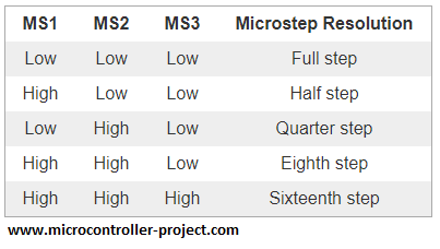
A4988 Stepper Motor Driver Resolution Control Logic
Design circuit
9 volt battery is used to supply power to the stepper motor. It is connected between the VMOT and GND pins of the A4988 stepper motor driver. 100 micro farad capacitor is inserted between the power rails to prevent power and AC surges. The Nema 17 stepper motor has 4 output pins/wires. Four wires means 2 pairs of coils. Each thread has a different color. Typically red and blue are one pair and green and black are another pair. In some engines, yellow is used instead of blue, and gray is used instead of black. Therefore, first ensure the winding of the coils before making any connections. A4988 stepper motor driver is powered with 3.3 volt output power supply from stm32 microcontroller. Stm32 also produces 5 volts. So if you want to power the motor driver with 5 volts, just change the connection. 3.3 volts worked for me. The Reset and Sleep pins are interconnected. The reset pin is a floating pin and the suspend pin is normally pulled up (see driver equivalent circuit above). So connecting Reset with Sleep makes the Reset pin high, now the driver will never reset. The enable pin is open. It is also internally pulled down, meaning the motor driver is always in enable mode.
I'm going to run the engine in Full Step mode. For full stepper mode, you need to leave the A4988 stepper motor driver mode pins low. Motor drive mode pins Ms1, Ms2, and Ms3 remain intact. They have remained open and work for me. Although it worked for me, I recommend connecting Ms1, Ms2 and Ms3 to ground for full step mode. Then Step pin of motor driver is connected to pin no.4 of Port A of stm32f103 microcontroller. The direction pin is connected to pin no.3 of Port A of the stm32 microcontroller. The circuit diagram of the project is given below.
I'm going to run the engine in Full Step mode. For full stepper mode, you need to leave the A4988 stepper motor driver mode pins low. Motor drive mode pins Ms1, Ms2, and Ms3 remain intact. They have remained open and work for me. Although it worked for me, I recommend connecting Ms1, Ms2 and Ms3 to ground for full step mode. Then Step pin of motor driver is connected to pin no.4 of Port A of stm32f103 microcontroller. The direction pin is connected to pin no.3 of Port A of the stm32 microcontroller. The circuit diagram of the project is given below.
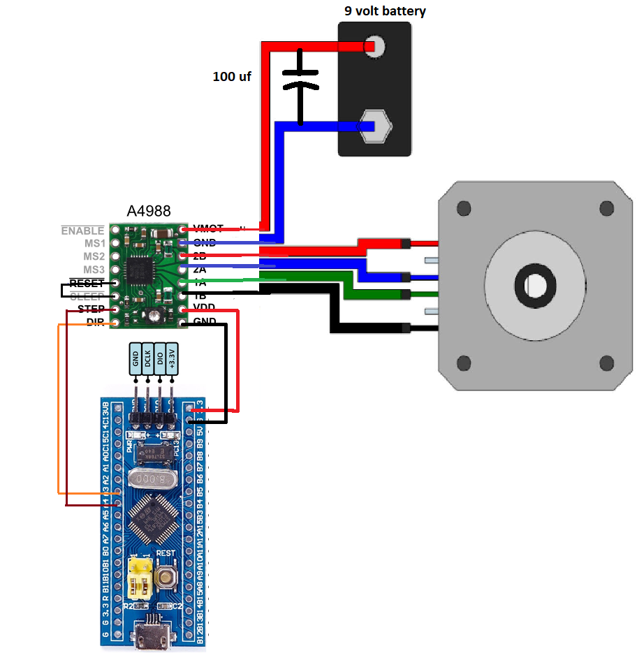
nema 17 stepper motor controlled with stm32 microcontroller
The project code is written and compiled in keil arm v5 ide. The Stm32cubemx code configurator is used to configure the stm32f103c8t6 settings. The internal 8 Mhz hc oscillator is used to provide the clock source for the microcontroller system, buses and other microcontroller peripherals. Two stm32 Port-A pins are declared as output and given names. If you are new and have no previous experience with Stm32cubemx, you should follow the getting started tutorial. After following the tutorial, you can easily understand the code instructions below. Click the button to do the tutorial.
The main logic of the above code is in the while(1) function. First, the steering pin is placed in the high position. This will set the stepper motor to move clockwise.
HAL_GPIO_WritePin(GPIOA, DIR_Pin, GPIO_PIN_SET); //Clockwise rotation
Then a for loop moves the engine. The for loop steps are provided to the engine. Remember that the nema 17 stepper motor takes 200 steps to give a full 360 degree rotation (1.8 degree step angle). Therefore, the for loop runs 200 times to complete one rotation. Then the steering pin is set to low level and now the motor will move back a few steps. In this state, the stepper motor also takes 200 steps. He returns to his starting position.
Future work
This tutorial is a basic lesson on how to operate a stepper motor with stm32 microcontrollers using keil ide and stm32cubemx. For the future you can test the stepper motor with micro steps. Change the A4988 modes and test each mode 1/4, 1/8 and 1/16. You can also change the rotation frequency or control the rotation speed of the shaft. As this tutorial is based on bipolar stepper motor, you can test unipolar motor in future with minor modifications to the circuit and code.
Download the project code. The folder contains the stm32cubemx and keil arm files. The code is open source. Please provide us with your feedback on the project.
Code/Files