 Block diagram –
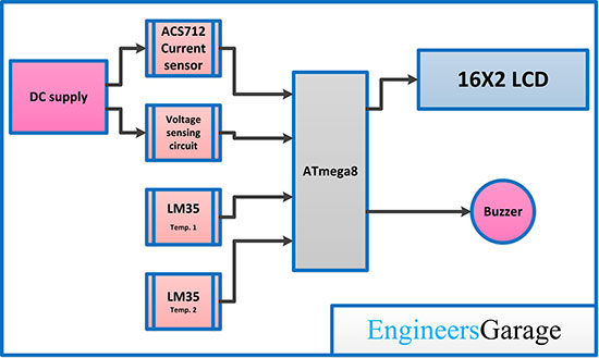
Fig. 1: Block diagram of VAT METER using ATMega8
Circuit Connections –
This device is based on the AVR ATMega8. ATMega8 is an 8-bit microcontroller that can operate up to 16 MIPS of transfer rate clocked at 16 MHz. Here we are using ATMega8's internal RC oscillator which provides fixed clock rate of 1.0 2.0 4.0 or 8, 0 MHz, then set your ATMega8 internal RC oscillator to 1 MHz.
ATMega8 is interfaced with 16×2 LCD, L M35 and ACS712 to make the device. There is a Trimpot (shown as VR1 in the circuit diagram) which is used to adjust the contrast of the LCD. There is a yellow LED with a parallel interface to the entire circuit that is used to indicate that the circuit's power supply is working properly. There is a blinker connected to bit 0 of port D of the ATMega8 which indicates that the MCU is working.
Two LM35 temperature sensors are used to obtain the temperature state at two different locations. Both LM35 are connected to bits 1, 2 of port C of the ATMega8, which are pins 1 and 2 of the ADC. The ACS712 current sensor is used to measure current through a series connection with a DC power supply. The OUT pin of the ACS712 is connected to bit 0 of port C of the ATMega8 which is pin 0 of the ADC. The voltage is measured by bit 3 of port C of the ATMega8, which is pin 3 of the ADC. diagram) which is used to calibrate the voltage.
The BC548 transistor is used to drive the buzzer. The base of the transistor is connected to bit 1 of port D of the ATMega8. The collector of the transistor is connected to the buzzer and the emitter is connected to ground. AREF or 21st pin of ATMega8 is connected to 5v via 10mH inductor and there is also a 0.1uf capacitor connected between ground and AREF. The entire circuit operates on 5V DC which can be obtained from a 5V power bank or 9V battery with 5V regulated power supply using 7805 IC. The internal RC oscillator (1 MHz) used with ATMega8, so there is no need to add external oscillator.
How the circuit works –
After assembling the circuit, the ISP port of the ATmega8 must be connected to any AVR programmer and the VATmeter.hex file must be updated on the microcontroller. Then disconnect the AVR programmer circuit. Now the device is ready for operation. When the device is turned on, the flashing LED starts flashing and the LED displays “Welcome to VAT METER”. After a few seconds, the LCD enters a stable state that displays the voltage, amp and temperature of both sensors and updates the data as per the sensor input update.
While we connect the DC power supply in series with the ACS712 current sensor as shown in the circuit diagram. The LCD shows battery voltage and current. Make sure the Load is connected in series with the battery and the ACS712 current sensor so that current can be measured through the Load. The temperature sensor can be placed close to the heating component to measure the temperature.
If the temperature exceeds 70 degrees centigrade or the voltage exceeds 45 VDC or the current exceeds 15 ACC, the display will flash the parameter close to the specific value and an audible signal will be generated via a buzzer.
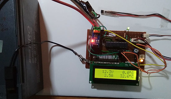
Fig.1: Image showing the operation of the VAT METER
Programming guide –
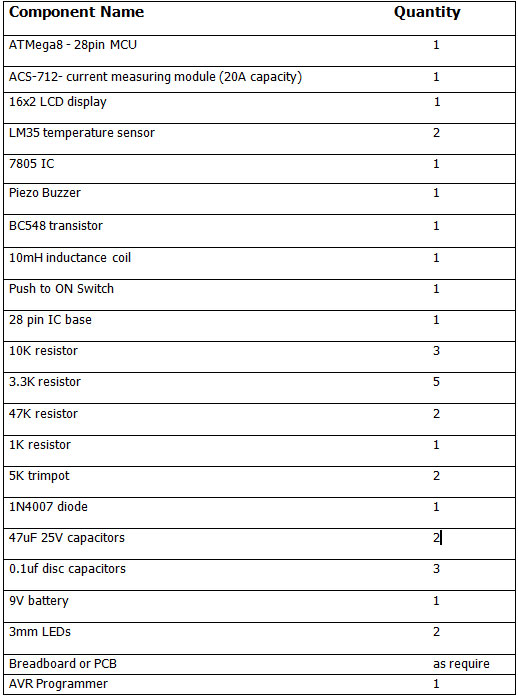
This device is based on AVR ATMega8 and is programmed with embedded C using AVR Studio 4. Other programming tools such as Atmel Studio or Notepad++ can also be used to write and compile the code. The ATMega8 is programmed to measure Voltage, Current and Temperature at the same time on a single display. This project can measure voltage up to 50Volts DC and maximum current up to 20Amps DC.
Constants used in the code –
#define F_CPU 1000000L :- Constant used to define the MCU clock frequency
#define BLINKER 0b00000001 :- defines the blinking LED for bit 0 of port D
#define ALARM 0b00000010 :- defines buzzer connected to bit 1 of port D
#define LCD_DP PORTB: – Port B defined as LCD data control port
#define LCD_CP PORTD: – Port D is defined as LCD control port
#define LCD_EN 0b10000000 : – The EN pin of the LCD is connected to 7 bits of port D
#define LCD_RS 0b01000000 : – The RS pin of the LCD is connected to 6 bits of port D
Variable used in the code –
AMP long = 488; : – To calculate ampere value to ADC value
internal VOLTS=0; : – To store the voltage value
long AMPS = 0L; : – To store the current value
intTEMP1=0; :- To store the temperature of the first sensor
int TEMP2 = 0; :- To store the temperature of the second sensor
char DST(8); :- To display the value on LCD
long A=0; : – To initially store the ADC value
inner loop = 0; :- To control the parameter blinking on the LED
internal alarm = 0; : – To control the doorbell
int temparray1(5)={25,25,25,25,25}; : – To store 5 temperature values for average temperature
int temporray1pos=0; :- To select temperature matrix value
int temparray2(5)={25,25,25,25,25}; : – To store 5 temperature values for average temperature
int temporray2pos=0; :- To select temperature matrix value
Header file and libraries used in the code –
#includeProject source code
###
//Program to / * filename: VATmeter.C author: f.hassan date: 10-03-2018 MCU: ATmeaga8 display: LCD 16x2 */ #define F_CPU 1000000L #define BLINKER 0b00000001 #define ALARM 0b00000010 //================================================ ================================= #include#include #define LCD_DP PORTB #define LCD_CP PORTD #define LCD_EN 0b10000000 #define LCD_RS 0b01000000 long AMPFACTOR = 488; // for 20A int VOLTS=0; long AMPS=0L; int TEMP1=0; int TEMP2 = 0; char DST(8); //================================================ ============================= void initPorts ( ) { DDRB = 0xFF; DDRD = 0xFF; DDRC = 0x00; } //================================================ ============================= void LCD_enable ( ) { LCD_CP = LCD_EN; _delay_us(50); LCD_CP &= (~LCD_EN ); _delay_us(30); } //================================================ =========================== void LCD_WriteCmd ( unsigned char cmd ) { LCD_CP &= (~LCD_RS ); LCD_DP = cmd; LCD_enable ( ); } //================================================ ============================= void LCD_init() { unsigned char initval = 0x30; _delay_ms ( 50 ); LCD_WriteCmd ( 0x30 ); _delay_ms ( 20 ); LCD_WriteCmd ( 0x30 ); _delay_us ( 200 ); LCD_WriteCmd ( 0x30 ); _delay_ms ( 100 ); initval = 0b00001000; initval = 0b00000100; LCD_WriteCmd ( initval ); _delay_ms ( 25 ); LCD_WriteCmd ( 0x0C ); _delay_ms ( 25 ); LCD_WriteCmd ( 0x06 ); _delay_ms ( 50 ); } //================================================ ============================= void LCD_RowCol ( unsigned char R, unsigned char C ) { switch (R) { case 2: LCD_WriteCmd ( 0xC0 + C-1 ); break; case 1: default: LCD_WriteCmd (0x80 + C-1); break; } _delay_ms ( 3 ); } //================================================ ============================= void LCD_ClrScr ( ) { LCD_WriteCmd ( 0x01 ); _delay_ms(3); } //================================================ ============================= void LCD_writeCh ( unsigned char ch ) { LCD_CP = LCD_RS; LCD_DP = ch; LCD_enable ( ); } //================================================ ============================= void LCD_writeStr ( char s ) { for (int i=0; s(i)!=0; i++) { LCD_writeCh ( s(i) ); _delay_us ( 20 ); } } //================================================ ======================================== void ADC_init ( ) { ADCSRA = ( (1 << ADPS2) (1 << ADPS1) (1 << ADPS0) (1 << ADEN) ); } //================================================ ======================================== int ADC_read (int cno) { ADMUX = (cno%4); ADCSRA = (1 << ADSC); while (ADCSRA & (1 << ADSC)); return ADC; } //================================================ ======================================== void showValue(int vin) { int V = vin; if ( V < 0 ) { DST(0)= '-'; V = V * -1; } else { DST(0)= ' '; } DST(1)=V/1000 + '0'; V=V%1000; DST(2)=V/100 + '0'; V=V%100; DST(3)=V/10 + '0'; DST(4)='.'; DST(5)=V%10 + '0'; DST(6)=0; if (DST(1) == '0' && DST(2) == '0') { DST(1) = ' '; DST(2) = ' '; } if (DST(1) == '0' ) DST(1) = ' '; LCD_writeStr ( DST ); } //================================================ ======================================== int main() { longA=0; int loop = 0; int alarm = 0; int temparray1(5)={25,25,25,25,25}; int temparray1pos=0; int temparray2(5)={25,25,25,25,25}; int temparray2pos=0; _delay_ms ( 100 ); initPorts ( ); PORTD = BLINKER; _delay_ms ( 2000 ); LCD_init ( ); _delay_ms ( 100 ); PORTD &= (~BLINKER); LCD_ClrScr ; LCD_RowCol ( 1, 1 ); LCD_writeStr ( "Welcome to" ); LCD_RowCol ( 2, 7 ); LCD_writeStr ( "VAT METER" ); ADC_init ( ); _delay_ms ( 2000 ); for (int i=0; i<10; i++) { ADC_read ( i/2 ); } LCD_ClrScr ; while(1) { if (loop==0) loop = 1; else loop = 0; alarm = 0; PORTD ^= BLINKER; A = ADC_read(3); _delay_ms ( 5 ); LCD_RowCol ( 1, 1 ); VOLTS = A / 2; showValue ( VOLTS ); if (VOLTS>450 && loop==0) { LCD_writeStr ( " " ); alarm = 1; } else LCD_writeStr("V"); A = 0; ADC_read ( 0 ); _delay_ms ( 5 ); for (int i=0; i<10; i++) { A = A + ADC_read ( 0 ); _delay_ms ( 5 ); } A = 5110-A; AMPS = (A * AMPFACTOR) /10000L; LCD_RowCol ( 2, 1 ); showValue ( AMPS ); if ( (AMPS>150 AMPS<-150) && loop==0) { LCD_writeStr ( " " ); alarm = 1; } else LCD_writeStr("A"); A = 0; ADC_read(1); _delay_ms ( 5 ); for (int i=0; i<10; i++) { A = A + ADC_read ( 1 ); _delay_ms ( 5 ); } TEMP1 = A/2; temparray1(temparray1pos++) = TEMP1; TEMP1 = (temparray1(0) + temparray1(1) + temparray1(2) + temparray1(3) + temparray1(4) )/5; if (temparray1pos>4) temparray1pos = 0; LCD_RowCol ( 1, 9 ); showValue ( TEMP1 ); if (TEMP1>700 && loop==0) { LCD_writeStr ( " " ); alarm = 1; } else { LCD_writeCh ( 223 ); LCD_writeCh ( 'C' ); } A = 0; ADC_read(2); _delay_ms ( 5 ); for (int i=0; i<10; i++) { A = A + ADC_read ( 2 ); _delay_ms ( 5 ); } TEMP2 = A/2; temparray2(temparray2pos++) = TEMP2; TEMP2 = (temparray2(0) + temparray2(1) + temparray2(2) + temparray2(3) + temparray2(4) )/5; if (temparray2pos>4) temparray2pos = 0; LCD_RowCol ( 2, 9 ); showValue ( TEMP2 ); if (TEMP2>700 && loop==0) { LCD_writeStr ( " " ); alarm = 1; } else { LCD_writeCh ( 223 ); LCD_writeCh ( 'C' ); } if (alarm) PORTD = ALARM; _delay_ms ( 150 ); PORTD &= (~ALARM); _delay_ms ( 60 ); } return 0; }
###
Circuit diagrams
| VAT_meter_circuit_IVA |  |