Interface accelerometer with NRF24LE1
In this series, we learn the basic functionalities and features of the NRF24LE1 . Now it's time to use them to perform higher tasks. In the future, we will combine various features of the NRF with the outside world. Today, we will interface an accelerometer sensor with NRF24LE1 using ADC (analog to digital converter). We will also send the acceleration reading to our PC using serial communication.

Fig. 1: NRF24LE1 interface prototype with accelerometer
See our previous articles on ADC and serial communication .
We have all studied the definition of acceleration, which says that it is the rate of change of speed. Previously, we used to calculate acceleration manually using formulas, but this is an era of digital world; sensors are now available to replace the manual task. These sensors have a wide range of applications, be it a robotic arm or a rocket. The accelerometer sensor we will use is the ADXL335.
Some basic features of ADXL335:
· 3-axis detection
· Low power – 350 uA (typical)
· 1.8V – 3.6V operation
· Small size
Detection range from -3g to +3g
Operation:
This module has 3 analog output pins for acceleration in the X, Y and Z directions. The output voltage on these pins ranges from 0 – 3.3V.

Fig. 2: PCB layout of NRF24LE1 interface with accelerometer
3.3V corresponds to +3g where g is the gravitational acceleration.
We will use NRF's built-in ADC to convert the analog voltage detected in the module and the reference voltage for ADC will be 3.3V. Analog pin X will be connected to Pin0.0, Y to Pin0.1 and Z to Pin0.2. The module for ADXL335 already has a built-in 3.3V regulator IC. So we will supply 5V to this module.
After getting the converted digital value for different directions, we have to subtract the 0g value from them. 0g means there is no acceleration, but the accelerometer sensor still outputs some analog voltage to it. So we have to reduce this value from the detected digital value.
The 0g output value can be found in the sensor datasheet. The 0g value we are using is 1.33 V for X, 1.6 V for Y, and 0.84 V for Z direction. The corresponding digital values are 103, 124, and 65.
After subtracting the 0g values, we will divide the result by the sensitivity of the sensor. Sensitivity is measured in mV/g. It can be found in the technical sheet. We are using a value of almost 300mv/g for Sensitivity. The corresponding digital value is around 23. After division, the result will be in terms of g.
Therefore, the formula for calculating acceleration is:
Acceleration in X= (x – 103.0)/23.0;
Acceleration in Y = (y – 124.0)/23.0;
Acceleration in Z = (z – 65.0)/21.0;
Where x, y and z are the analog values detected in the module.
We will transmit the calculated acceleration to the PC via serial communication. The pin for serial transmission is P0.3. We have also mentioned the code for clearer understanding.
Project source code
###
//Program to/* Copyright (c) 2009 Nordic Semiconductor. All rights reserved.
*
###
Circuit diagrams
| Circuit Diagram-NRF24LE1-Accelerometer Interface | 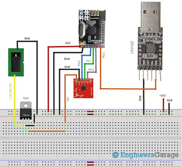 |
Project video