When it comes to efficient control and starting of electric motors, direct starting, commonly known as DOL starting, plays a crucial role. This article will give you an in-depth understanding of DOL starter control wiring, its construction, circuit diagrams, operating principles, applications, and more. Whether you are an electrician, engineer, or simply someone interested in the world of electrical controls, this guide will provide you with valuable information.
What is a DOL initiator?
A direct on-line starter (DOL starter) is a widely used electrical device that allows direct starting of electric motors. It is a simple and economical method for starting motors, especially in applications where precise control is not required.
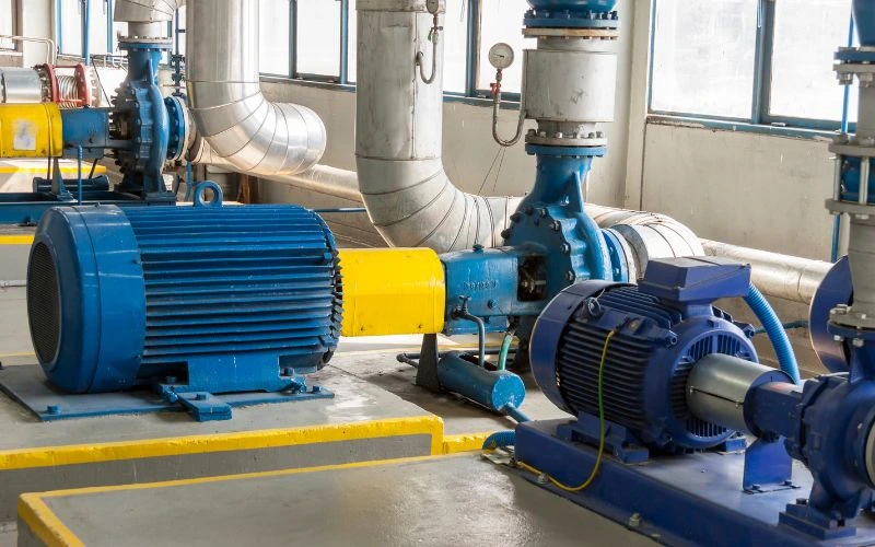
DOL starters are often used in situations where a motor must start at full voltage and provide maximum torque immediately. This is often the case in applications such as conveyors, pumps, fans and compressors.
Structure and parts of a DOL starter
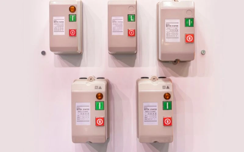
A DOL starter consists of several important components, including:
- Contactor: This is the heart of the DOL starter motor and is responsible for connecting and disconnecting the motor from the supply. When the start button is pressed, the contactor closes, allowing current to flow to the motor.
- Overload relay: Protects the motor by tripping when overload is detected. Overload protection is important to prevent the motor from burning out due to excessive current.
- Start and stop buttons: These buttons allow you to manually control engine operation. The start button starts the engine and the stop button turns it off.
- NO (Normally Open) and NC (Normally Closed) Contacts: These contacts play a role in the control circuit and are essential for safety. Normally open contacts are used to bypass the start button after it is pressed, ensuring the engine remains connected even when the button is released. Normally closed contacts can be used for additional control functions.
- Terminal Blocks: They provide connection points for input and output power, facilitating correct wiring of the DOL starter.
DOL starter wiring diagram
Correct wiring of a DOL starter is essential for safe and efficient engine operation. Here are step-by-step instructions to help you with the wiring:
Table: DOL Starter Cable Connections
| Terminal label | Purpose of the connection | Cable color |
|---|---|---|
| L1 | Input line 1 | Red |
| L2 | Line 2 input | Yellow |
| level 3 | Line 3 input | Blue |
| T1 | Motor terminal 1 | Black |
| T2 | engine terminal 2 | White |
| T3 | engine terminal 3 | Brown |
- Connect line input: Connect the power supply cables to the L1, L2 and L3 terminals of the DOL starter. Pay attention to the correct color coding of the phases.
- Connect the motor terminals: Connect the motor cables to the corresponding terminals T1, T2 and T3 on the DOL starter. Properly protect and isolate these connections.
- Overload Relay Wiring: Connect the overload relay to the DOL starter control circuit according to the manufacturer's instructions. Make sure it is set to the appropriate current level to adequately protect the motor.
- Control Circuit Wiring: Connect start and stop buttons and other control devices according to the DOL starting diagram provided by the manufacturer. Make sure the control circuit is properly grounded.
- Check and secure connections: Before turning on the system, double-check all connections to ensure they are secure and insulated. Loose or exposed wires can cause electrical hazards and malfunctions.
Carefully following the wiring diagram is important to prevent electrical accidents and engine damage and to ensure that the DOL starter operates as intended.
Wiring diagram for three-phase DOL starter
For three-phase motors, the DOL starter wiring diagram requires that all three phases of the motor be connected to the starter. This ensures that the motor receives power evenly across all phases, allowing for smooth, balanced operation. Here is a simplified overview of the wiring process for a three-phase DOL starter:
- Connect the three-phase power supply: Connect the L1, L2 and L3 terminals of the DOL starter to the corresponding phases of the three-phase power supply.
- Connect the motor terminals: Connect the three motor phases to the T1, T2 and T3 terminals of the DOL starter.
- Connect the overload relay: Connect the overload relay to the control circuit and make sure it is set to the appropriate current rating for the motor.
- Control circuit wiring: Connect the start and stop buttons to the control circuit, ensuring proper grounding and safety measures.
- Double-check connections: Before turning on the system, carefully check all connections and make sure they are secure and insulated.
Single Phase DOL Starter Wiring Diagram
In cases where single-phase power is available or when dealing with single-phase motors, a different wiring configuration is used. Here is a simplified overview of the wiring process for a single-phase DOL starter:
- Connect the single-phase power supply: Connect the L1 and L2 terminals of the DOL starter to the single-phase power supply.
- Connect the motor terminals: Connect the two motor connection terminals to the T1 and T2 connection terminals of the DOL starter.
- Connect the overload relay: Connect the overload relay to the control circuit and adjust it to the appropriate current for the motor.
- Control circuit wiring: Connect the start and stop buttons to the control circuit, ensuring proper grounding and safety measures.
- Double-check connections: Before turning on the system, carefully check all connections and make sure they are secure and insulated.
To avoid accidents and ensure proper engine operation, it is important to use the correct wiring diagram and follow safety guidelines when working with single-phase DOL starters.
DOL starter working principle
The operating principle of a DOL match is relatively simple. When the start button is pressed, the contactor closes and connects the motor to power. At the same time, the NO (normally open) contacts bypass the start button and maintain the connection even if the button is released. To stop the engine, the stop button is pressed, which opens the contactor and breaks the circuit.
Here is a step-by-step explanation of the working principle of the DOL starter:
- Idle state: In standby mode, the contactor remains open and the motor is not connected to the electrical network. The overload relay is ready to detect excessive current.
- Start Operation: When the Start button is pressed, the control circuit activates the contactor coil and causes it to close. This connects the motor to the power source and allows current to flow.
- NO contacts: NO (Normally Open) contacts bypass the start button and ensure the engine remains connected even when the start button is released.
- The engine is running: The engine starts at full voltage and provides the torque required for the intended operation.
- Stop operation: To stop the engine, the stop button is pressed. This interrupts the control circuit, de-energizes the contactor coil and opens the contacts. This will disconnect the motor from the power source.
The simplicity and reliability of the DOL starter's operating principle make it suitable for numerous applications where full voltage starting is acceptable.
DOL Initial Applications
DOL starters are used in a variety of industrial and commercial environments, including:
- Pumps and compressors: DOL starters are often used to control pump and compressor motors.
- Fans and blowers: These starters are ideal for applications where simple on/off control is sufficient, such as in HVAC systems.
- Conveyors and Agitators: DOL starters provide reliable motor control for conveyor belts and agitators in manufacturing processes.
- Machine tools: Many machine tools use DOL starters to control motors in shops and factories.
Conclusion
In summary, understanding DOL starter motor control wiring is essential for anyone involved with engine control systems. Whether you are setting up a new engine or repairing an existing engine, the knowledge provided in this article will be invaluable. Therefore, carefully follow the wiring diagrams and consider the specific requirements of your engine application for safe and efficient operation.
Common questions
Can a DOL starter be used for single-phase and three-phase motors?
Yes, DOL starters can be used for single-phase and three-phase motors if proper wiring configurations are followed. Single-phase motors require different wiring than three-phase motors.
What is the purpose of the overload relay in a DOL starter?
The overload relay in a DOL starter is designed to protect the motor from overheating and damage by tripping the circuit in the event of an overload. It acts as a safety mechanism to prevent the engine from burning out.
Are there alternatives to DOL starters for motor control?
Yes, alternatives such as star-delta starters and soft starters offer advanced motor control options. Star-delta starters are used for applications where reduced voltage starts and gradual acceleration are required. Soft starters provide even more precise control by gradually increasing motor voltage and current, reducing starting current and mechanical stress.