There have been continuous innovations in the automotive industry, be it the use of Near Field Communication in upcoming car models or futuristic autonomous cars. These innovations are driven by one reason: to make driving increasingly comfortable and smarter or safer. This project is also a similar attempt to make car driving safer by modifying the headlights to adaptive headlights.
The headlights of any car are usually fixed. Therefore, while turning the car during night driving, drivers face problems as the fixed headlights are not actually illuminating the path where the driver is turning. This makes night driving prone to accidents and the driver needs to take corners with extra caution. If the headlights are rotated along with the direction the car has turned, the driver can have a full view of the actual path he is traveling around corners. This is possible by mounting the headlights on servo motors and automating the servos in coordination with the car's steering. The steering movement can be plotted using a mechanical assembly coupled to a potentiometer.
In this project, this innovation was carried out using Arduino boards and connecting the servo motor circuit to the control circuit installed in the steering through the 434 RF Module. Instead of modifying a car body to change the headlight mounting, the project demonstrated the application using LEDs mounted on RC servos. The control circuit is also not manufactured with complete mechanical assembly in one direction, but a potentiometer is used in the design to illustrate the rough operation. However, the project can gain real size by implementing the modification of the car body by mounting rotating headlights on the car and installing the control circuit with suitable mechanical mounting on the steering.
Required components
| Mr. No. | Required components | Amount |
|---|---|---|
| 1 | RF Rx Module (434Mhz) | 1 |
| two | RF Tx Module (434Mhz) | 1 |
| 3 | Arduino for mini | two |
| 4 | LED | two |
| 5 | 10k pot | 1 |
| 6 | servo motor | two |
| 7 | Battery – 9V | two |
| 8 | Test board | two |
| 9 | Connecting wires |

Figure 1: Block diagram of Arduino-based adaptive headlights for cars
Circuit Connections
There are two circuits in the project – Steering Control Input Circuit and Headlight Servo circuit. In the direction control input circuit, a 10K ohm potentiometer is connected to the analog pin A2 of the Arduino Pro Mini. The other two terminals of the potentiometer are connected to VCC and ground. The Arduino interfaces with the RF transmitter by connecting the serial input pin (pin 2) of the RF transmitter to pin 12 of the Arduino. An antenna can be used on pin 4 of the RF transmitter to improve signal transmission, but it is optional and not really necessary as the operational range of the project will be limited to the frontal dimensions of the car. In implementing the full-size project, some mechanical assembly needs to be designed so that the potentiometer knob rotates in relation to the steering wheel rotation.
In the Servo circuit, an RF receiver is connected to another Arduino board by connecting the serial output pin (pin 2) of the receiver module to pin 11 of the Arduino. Again, an antenna can be used with the RF receiver, which is optional only to improve signal strength. There are two LEDs connected to pins 9 and 7 of the Arduino which are considered the car's headlights in the circuit. These LEDs are mounted on the servomotors. There are two RC servo motors connected to data pins 5 and 6 of the Arduino in relation to the beacon representing the LEDs.

Fig. 2: Prototype Transmitter Circuit for Adaptive Car Headlights
How the circuit works
To understand how this project works, it is important to understand how a potentiometer works. The potentiometer is a strip of resistance material. It is one terminal connected to the anode and another terminal connected to the cathode. The voltage output is taken from a third terminal that has sliding contact with the resistive material. As the contact closes at the anode end, the voltage output approaches the supply voltage due to the low resistance. When the contact moves away from the anode end, the output voltage drops due to a higher resistance between the anode and the output terminal, because the resistance increases in proportion to the length of the resistive material between them. At the steering end, the potentiometer is set to an average value by default, as the steering turns in either direction, the potentiometer contact slides out or approaches the anode end and the potentiometer output voltage is reduced or increased by relative to the default value.
The voltage output from the potentiometer is read as analog data on the Arduino pin A2 on the transmitter side. The reading is converted to character format and transmitted via RF using VirtualWire library functions in the program code.
The potentiometer reading is detected at the RF receiver and sent in series to pin 11 of the Arduino on the receiver side. The program code on the receiver side of the Arduino detects the potentiometer reading by reading the buffer of transmitted characters and converting the reading to an integer value. The value is compared with a standard calibrated value and the direction of rotation is evaluated accordingly. Upon detecting the direction the car turned, PWM signals are transmitted to the RC servos to rotate along the turning direction. The LEDs remain lit by default and rotate with the servo as they are mounted on them. Check out the Arduino code on the transmitter side to see how the analog potentiometer reading is detected in the code and converted into character form and transmitted serially over RF. Then check the receiver side Arduino code to know how the character buffer is read and interpreted to an integer value and based on the read value, the servos are operated.

Fig. 3: Receiver Circuit Prototype for Adaptive Car Headlights
Programming Guide
On the Arduino transmitter side, first, the program code imports the necessary standard libraries. The VirtualWire library is required to read the analog readout from pin A2. The global variables ledPin and Sensor1Pin are declared and mapped to pin 13 where the transmission progress indicator LED is connected and pin A2 where the potentiometer output pin is connected respectively. A Sensor1Data variable is declared to store the potentiometer voltage reading. A Sensor1CharMsg character array is declared for stored decimal representation of the potentiometer reading.
A setup function is called where the LED indicator pin is set to output while the pin connected to the sensor is set to input mode using the pinMode function. The Arduino baud rate is set to 9600 bits per second using the serial.begin function. The baud rate for serial output is set to 2000 bits per second using the vw_setup function of the VirtualWire library.
A loop function is called where the analog reading (in terms of measuring voltage at the pin) is obtained using the analogRead function and stored in the “Sensor1Data” variable. The potentiometer reading (an integer value) is converted to the base 10 character using the itoa function and stored in the Sensor1CharMsg array.
The potentiometer reading is serially output as human-readable ASCII text using the Serial.print and Serial.println functions.
The transmission progress indicator LED is turned on by passing a HIGH to pin 13. The character message containing the potentiometer reading is sent serially using the vw_send function and vw_wait_tx is used to block transmission until a new message is available for transmission . The LED on pin 13 is turned off by passing a LOW to indicate successful transmission of the message.
This ends the Arduino code on the transmitter side.
On the receiver side Arduino, the program code first imports the required standard libraries. The VirtualWire library is imported to receive readings from the RF potentiometer. The pins where the servos are connected are mapped to variables “servo” and “servo1” and other global variables – “angle” to represent the rotation angle of the servos and “PWM” to the respective pulse width duration are declared. The “Sensor1Data” is declared to store the integer value of the reading and the Sensor1CharMsg array is declared to contain the character representation of the reading through RF.
A setup function is called where the Arduino baud rate is set to 9600 bits per second. The pins connected to the servo and LED are configured for digital output using the pinMode functions. The pins where the LEDs are connected are set to HIGH to keep the LEDs on by default.
The RF transmitter and receiver module does not have a Push To Talk pin. They are inactive when no data is present to transmit or receive respectively. Therefore, vw_set_ptt_inverted(true) is used to set the push to talk polarity and request the receiver to continue receiving data after fetching the first character. The baud rate for serial input is set to 2000 bits per second using the vw_setup function. Data reception is started using vw_rx_start .
The null character is detected in the buffer stream so that no garbage values are stored. The characters received from the buffer are converted to the integer value and stored in the “Sensor1Data” variable.
The variable value along with the included relevant strings is passed to the microcontroller buffer and the Sensor1Data value is passed to the servoPulse and servoPulse1 custom functions as a parameter to rotate servos.
In the servoPulse function, the Sensor1Data that was passed as the angle parameter is taken and multiplied by 11 and then added to 1000 to get the pulse width duration in microseconds. The pin connected to the servo is set to HIGH and the calculated duration delay is passed. The HIGH output to the pin connected to the servo is then terminated.
The same logic implemented in the servoPulse function is implemented as in the servoPulse1 function.
This ends the Arduino code on the receiver side.
Project source code
###
#include// LED's const int ledPin = 13; // Sensors const int Sensor1Pin = A2; // const int Sensor2Pin = 3; int Sensor1Data; //int Sensor2Data; char Sensor1CharMsg(4); void setup { // PinModes // LED pinMode(ledPin,OUTPUT); // Sensor(s) pinMode(Sensor1Pin,INPUT); // for debugging Serial.begin(9600); // VirtualWire setup vw_setup(2000); // Bits per sec }void loop { // Read and store Sensor 1 data Sensor1Data = analogRead(Sensor1Pin); // Convert integer data to Char array directly itoa(Sensor1Data,Sensor1CharMsg,10); // DEBUGSerial.print("Sensor1 Integer: "); Serial.print(Sensor1Data); Serial.print(" Sensor1 CharMsg: "); Serial.print(Sensor1CharMsg); Serial.println(" "); delay(10);// END DEBUG digitalWrite(13, true); // Turn on a light to show transmitting vw_send((uint8_t *)Sensor1CharMsg, strlen(Sensor1CharMsg)); vw_wait_tx ; // Wait until the entire message is gone delay(12);} // END void loop... #includeint servant = 5; int servo1 = 9; intangle; int pwm; // Sensors int Sensor1Data; // RF Transmission container char Sensor1CharMsg(4); void setup { Serial.begin(9600); pinMode(servo, OUTPUT); pinMode(servo1, OUTPUT); pinMode(3, OUTPUT); pinMode(8, OUTPUT); digitalWrite(3,HIGH); digitalWrite(8,HIGH); // sets the digital pin as output //VirtualWire // Initialize the IO and ISR // Required for DR3100 vw_set_ptt_inverted(true);// Bits per sec vw_setup(2000); // Start the receiver PLL running vw_rx_start ; } // END void setup void loop { uint8_t buf(VW_MAX_MESSAGE_LEN); uint8_t buflen = VW_MAX_MESSAGE_LEN; // Non-blocking if (vw_get_message(buf, &buflen)) {int i; // Message with a good checksum received, dump it. for (i = 0; i < buflen; i++) { // Fill Sensor1CharMsg Char array with corresponding // chars from buffer. Sensor1CharMsg(i) = char(buf(i)); }// Null terminate the char array // This needs to be done otherwise problems will occur // when the incoming messages have fewer digits than the // one before. Sensor1CharMsg(buflen) = ''; // Convert Sensor1CharMsg Char array to integer Sensor1Data = atoi(Sensor1CharMsg); // DEBUG Serial.print("Sensor 1: "); Serial.println(Sensor1Data); servoPulse(servo, Sensor1Data); servoPulse1(servo1, Sensor1Data); }} void servoPulse(int servo, int angle) { pwm = (angle*11) + 1000; // Convert angle to microseconds digitalWrite(servo, HIGH); delayMicroseconds(pwm); digitalWrite(servo, LOW); delay(15); // Refresh cycle of servo } void servoPulse1 (int servo1, int angle) { pwm = (angle*11) + 1000; // Convert angle to microseconds digitalWrite(servo1, HIGH); delayMicroseconds(pwm); digitalWrite(servo1, LOW); delay(15); // Refresh cycle of servo }
###
Circuit diagrams
| Circuit Diagram-Adaptive Headlights for Arduino Based Cars | 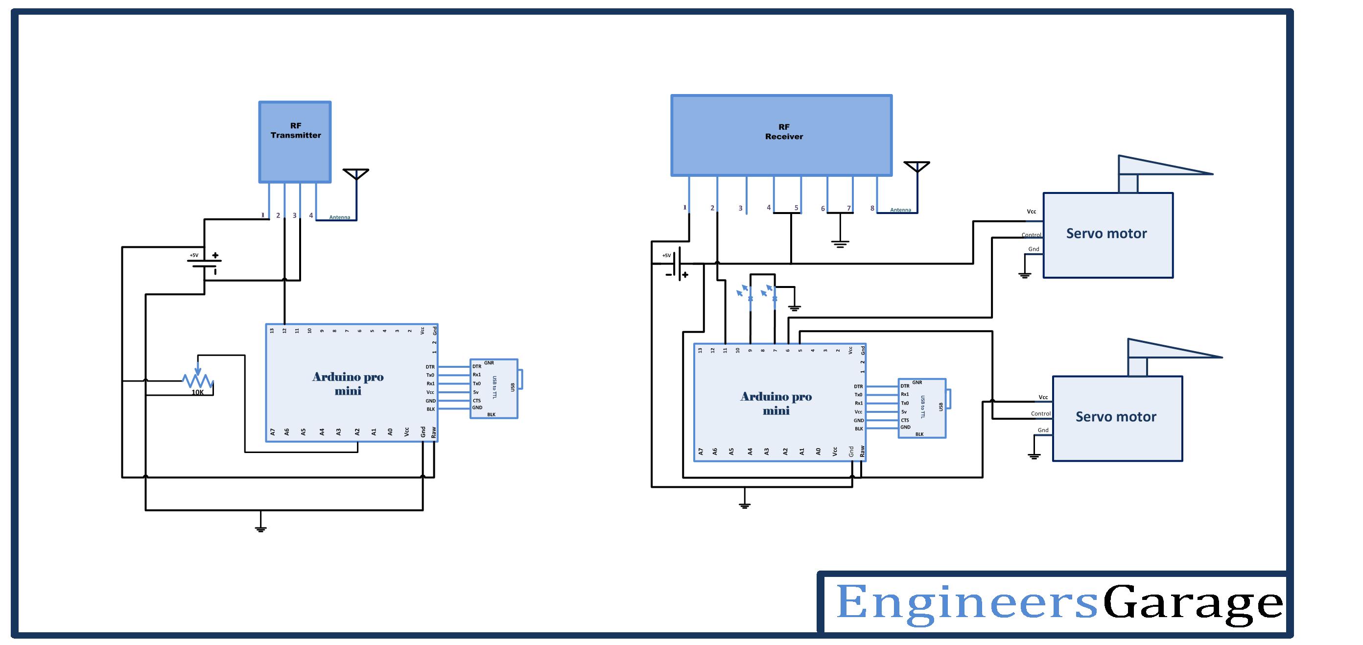 |
Project video