Have you ever had trouble driving nails into a wall perfectly parallel to the floor or ceiling? In this project, we model an electronic level device useful for placing anything perfectly parallel. This device is prototyped on the popular microcontroller board – the Arduino. It uses few components to build, just an accelerometer sensor and an LED light. Let's quickly build this device on our favorite Arduino UNO and get everything lined up perfectly.
Required components
- Arduino UNO x1
- ADXL345 Accelerometer Sensor x1
- LEDx1
- Resistance 330Ω x1
- Breadboard or prototyping board
- Connecting wires or jumper wires
- L-shaped measuring scale
Circuit Connections
This device is built by connecting Arduino with an ADXL345 accelerometer sensor and an LED. The ADXL345 is a digital sensor that communicates with Arduino via an I2C interface. To interface the ADXL345 with Arduino, connect the sensor's SDA and SCL pins to the SDA and SCL pins of one of the Arduino's I2C ports. The following image shows the I2C ports available on the Arduino UNO.

The VCC and GND pins of the ADXL345 are connected to the 5V output and one of the ground pins of the Arduino UNO. An LED also interfaces with the Arduino at pin 2. The anode of the LED is connected to 5V of the Arduino UNO output, while its cathode is connected to pin 2 of the Arduino. There is a 330Ω current limiting resistor in series with the LED.
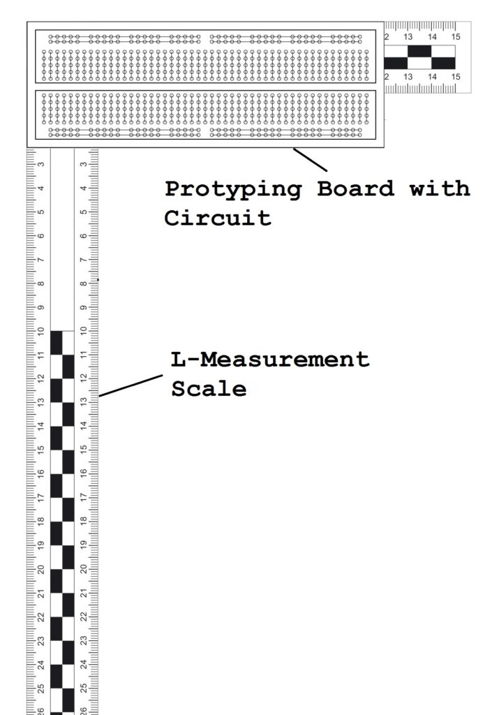
It is recommended to assemble the circuit on a prototyping board and attach a measuring scale L to the board. The measuring scale L must be perfectly aligned with the edges of the prototyping board or the overall housing of the device.
Circuit Diagram

Arduino Sketch
How it works
ADXL345 is a 3-axis MEMS accelerometer sensor. It is a digital inertial sensor that uses a capacitive accelerometer design. It has a user selectable range of up to +/- 16g, a maximum output resolution of 13 bits, a sensitivity of 3.9 mg/LSB, and a maximum output data rate of 3200 Hz. ADXL345 measures static acceleration due to gravity, as well as dynamic acceleration resulting from movement or shock. It can detect linear acceleration in 3 axes and detect the tilt and free fall of an object. The acceleration value obtained in units of gravity can vary from +2 g to -2g, or +4g to -4g, or +8g to -8g or +16g to -16g, depending on the selected measurement range. The acceleration value includes static accelerations due to gravity and dynamic acceleration due to motion or shock. The following image shows the acceleration values in gravity units due to gravity –
The tilt of the sensor can be detected by the sign and value of the acceleration in the x, y and z axes. When only static acceleration is working on the ADXL345 sensor, the acceleration value along a given axis will be approximately +1g or -1g.
By examining the acceleration signal and value in all axes, the exact orientation of the ADXL345 sensor in a 3-axis frame can be determined. This project uses the same principle of examining the orientation of the ADXL345 sensor. Whenever the sensor is perfectly aligned with one of the planes, the acceleration value in one of the axes will be 1, while in the other two axes it will be 0.
The Arduino is programmed to detect when the ADXL345 is perfectly tilted in one of the three planes. Remember that our circuit is also perfectly tilted with an L measurement scale. So, when perfectly tilted in one of the three planes, the Arduino lights up the LED indicator. This will indicate that the device and measuring scale L are perfectly parallel to a horizontal or vertical plane. Using the measuring scale L, points parallel to the horizontal or vertical plane can be marked. This can be used to drive nails perfectly parallel to the floor or ceiling or to place objects perfectly parallel to the ground. It can also be used to detect whether a wall or floor is sloped or flat.
In the Arduino code, we consider some tolerance of 5% to 10% in acceleration values, as we only need to determine situations where one of the acceleration values approaches 1 or -1. In contrast, the other two acceleration values approach a value of zero. Whenever these conditions are met, the LED turns on for 5 seconds and then turns off. This constant search for corresponding conditions helps to avoid human errors in marking parallel points.
The code
The Arduino sketch configures the ADXL345 sensor for a measurement range of +/- 2g and uses a 10-bit resolution. The script reads acceleration data from all axes and converts it to gravity units. Acceleration values on the x, y and z axes are 10 bits and right justified. Consequently, values are derived from 16-bit registers. In 10-bit resolution, the acceleration value in the unit of gravity is obtained by multiplying by 4 mg, that is, by multiplying by 0.004. After obtaining the acceleration values for all axes, the correspondence conditions are consulted, that is, whether one of the acceleration values approaches 1 or -1. In contrast, the other two acceleration values approach zero. If either matching condition is found to be true, the device and measuring scale L will be perfectly inclined with respect to the horizontal or vertical plane in space, and parallel points can be marked using the L scale.
The correspondence of the conditions is indicated by the lighting of an LED. The LED is connected to the Arduino in such a way that it absorbs the current from the Arduino pin. The LED lights up for 5 seconds setting the Arduino pin to LOW. Then, the LED is turned off again by setting the respective Arduino pin to HIGH. The accelerometer sensor is configured in the setup function. The acceleration values on the X, Y and Z axes are determined in the loop function. The corresponding conditions are also looked up in the loop function, so the Arduino keeps repeating them.
Result