Controlling LED brightness using meditation and attention level
SUMMARY

Fig. 1: Image showing the brightness of an LED being controlled by the meditation level using a brainwave sensor
Dramatically, when the signal strength is 100%, the sensor sends the value 0 and when the sensor sends 200, it means there is no connection of the metal sensor with our brain. So, after confirming that our signal strength is 100% and that our sensor is sending 0 in series for signal strength, we can perform this experiment.
Now as we know that PWM has a duty cycle that determines the analog level. The duty cycle is basically the time divided by the total period. To change the LED brightness based on attention level, we will change the PWM duty cycle.
Since we are getting the sensor meditation value on a scale of 0 to 100, we will make the duty cycle value equal to the meditation value subtracted from 100. For example, if the sensor meditation value is 40, then the duty cycle is 100–40 = 60.

Fig. 2: Image showing the brightness of an LED being controlled by the Meditation Level using the Brainwave Sensor
This will make the LED brightness parallel to the meditation level. You can check the code and video of this experiment. After the meditation level, we will do the same with the attention level. Just to remind you again, check if the signal strength is reaching 100% and with a value of 0.

Fig. 3: Image showing the brightness of an LED being controlled by the Meditation Level using the Brainwave Sensor
We again need to remove the attention values from the sensor and change the PWM duty cycle in relation to the attention values. Again, make the duty cycle value equal to the attention value subtracted from 100. For example, if the sensor meditation value is 40, the duty cycle will be 100 – 40 = 60.
Check out the software section to see how PWM is implemented in code.
And we also finish the brightness control using attention values. Check out the code and video to perform the experiment yourself.

Fig. 4: Block diagram of LED brightness controller based on MindFlex Brainwave sensor
Hardware: Please find the attached circuit diagram of the connections we need to make. We take a pin from the T pin of the mindflex sensor and connect this pin to the Rx pin of our Arduino UNO. Additionally, we short-circuited the Sensor and UNO ground by a wire. Please take special care when soldering anything to the Mindflex sensor as the pins are very close to each other.
Programs: Let's go to the software part. We have been receiving the E meter values from the sensor to our arduino via T pin. Once we receive the value at any specific point, we just need to convert that value level to the LED brightness. As discussed earlier, we will use PWM techniques. PWM on Arduino is done by analogWrite: E.g.
AnalogWrite(13,240);
AnalogWrite in Arduino is used to write PWM wave to a pin. In the example above, the first parameter is the PIN number and the second is the PIN value. So we are writing 240 on pin 13. Now we can easily calculate the analog voltage at value 240. The total voltage range is 0V to 5V and the value range is 0 to 255.
This means 240 = (5/255)*240 = ~4.70V.
Now, the values we get for and meters are in the range 0 to 100.
So let's say we get evalue = 70.
We will multiply the value of e by 2.55 to put it in the range 0 to 255.
So it will be analogWrite (pin,evalue*2.55) in a loop.
Some points to note:
The sensor usually provides 60 to 80% resistance due to its orientation and the location where we place it. Try to keep the metal sensor exactly above your left eye. I also applied salt water to my forehead for better connectivity with the sensor. If you don't find 100%, then it's normal. In the next articles, I will explain how we can control various objects without signaling attention and meditation values.
The signal strength also messes with how we solder the wire to the T pin. Try shielding this wire and also make sure the reference probes are connected correctly. If you have any wires connected to the sensor's EEG Pin, disconnect that wire, as this will create noise in the sensor values.
Try this experiment and let me know if you have any problems. Stay tuned for more Brainwave-based experiments related to controlling a motor.
Project source code
###
//Program to#include
###
Circuit diagrams
| Circuit-Diagram-MindFlex-Brainwave-Sensor-LED-Brightness-Controller | 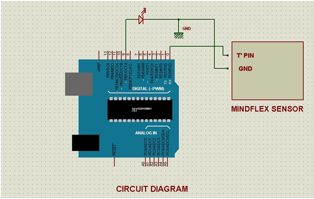 |