In Part 1 of this series, we reviewed the optimal selection parameters of a heatsink and cooling fan. In this article, we will discuss a thermoelectric refrigerator (TEC). TEC can be used in heating or cooling systems in applications where temperature stabilization or cooling below ambient temperature is required.
In this tutorial, we will use a TEC for liquid cooling applications and discuss the pros and cons of TEC.
1. TEC Principle
TEC works based on the principle of the Peltier Effect, which states that if a DC current is applied to two different materials, it causes a temperature difference. For this we will use Peltier thermoelectric material.
Peltier is made using two ceramic wafers with P- and N-doped semiconductor materials, connected in series and sandwiched between them. The N-type semiconductor has an excess of electrons and the P-type has a deficit of electronics. By increasing the number of P and N semiconductors, more temperature differences can be created.
The amount of temperature difference developed in the Peltier material is proportional to the current flowing through it. The negative side of the Peltier gets colder while the positive side gets hotter. By reversing the direction of current flow, it is possible to heat the colder side and cool the hotter side.
2. What is needed for Peltier material to work properly
A typical Peltier can generate a temperature difference of 70°C between its two surfaces. For it to function properly, it is necessary to remove heat from its hottest side. Otherwise, the Peltier will reach a state of equilibrium and do nothing.
So we will need to add a heatsink on the hotter side (to extract any extra heat). We will also use a cooling fan, alongside the heatsink, to ensure that any excess heat is dispersed into the surrounding air.
Peltier Applications
Peltier can be used for heating, cooling and power generation. It can convert electrical energy into heating or cooling and vice versa. The conversion of temperature to power is called the Seebeck Effect.
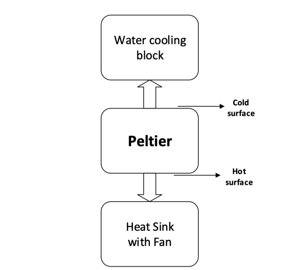
3. Thermal schematics of our system

Figure 1. Thermal schematic system block diagram
Circuit connection

Figure 2. Circuit diagram of a thermoelectric refrigerator
Required Parts
1. The Peltier – CP150
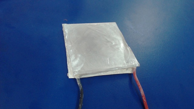
Figure. 3. Peltier – CP150
2. A 12V DC heatsink and cooling fan

Figure 4. 12V DC heatsink and cooling fan
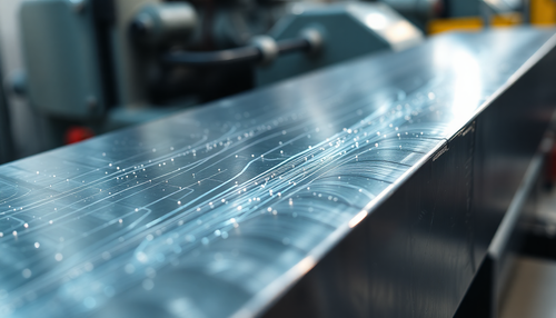
3. An aluminum water cooling block

Figure 5. Aluminum water cooling block
4. A 12V/10A power supply
Driving the Peltier
Peltier requires a current source for operation. Below are the methods by which we can operate Peltier.
1. A current source
By applying a constant current to a Peltier, it is possible to generate a temperature difference between it. To properly measure the amount of current required to generate a specific temperature, we will use a characteristic curve, which is typically provided in a Peltier datasheet (like below).
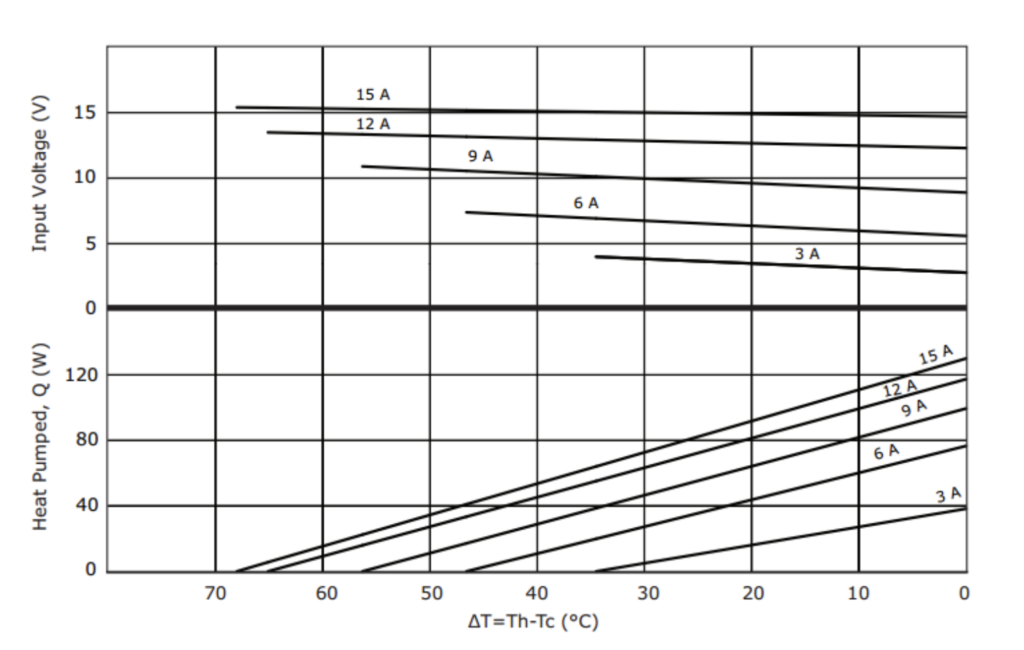
Figure 6. The characteristic curve necessary to generate a specific temperature for the Peltier
2. The voltage source
If we have a voltage source, then we can operate the Peltier through a pulse width modulation (PWM) signal. By varying the voltage, it is possible to control the flow of current throughout the Peltier.
3. The Peltier with driver
Depending on the Peltier application, it is possible to operate it with or without a driver circuit.
Operating modes
1. An open thermal loop system
When Peltier is operated without any feedback network, the system is considered an open-loop system. However, this system cannot regulate or control the temperature developed through the Peltier.
2. A closed thermal loop system
To maintain a constant temperature for the Peltier, it is possible to use a driver that is an H-bridge circuit.
When any of the Peltier surfaces become hotter or colder above its set point, the material detects this change via a temperature sensor. The driver will then respond to this by changing the direction of current flow – thus maintaining a constant temperature.
Trying Peltier
For this tutorial, we use Peltier in an open loop system to cool water. We mounted a cooling fan on the warmer side of the Peltier and added a two-way aluminum water block to the cooler side.
Additionally, we use a voltage source for power supply. Below are the results.
Results
| Input Voltage | Output current |
Temperature differences |
| 12V | 7.15A | 10° |
Application
- CCD Cameras
- Laser and amplifiers
- Refrigerator and water dispensers
- Avionics
Benefits
- Reduced size and weight compared to a typical mechanical system
- Unlike a heatsink, provides cooling below ambient temperature
- The ability to cool and heat at the same time
- Precise temperature control using closed-loop thermal control
- Can be used with DC power supply or PWM signals
- Can generate electrical energy
- Reliable
- Environmentally friendly and does not generate gas like a conventional refrigerator
Disadvantages
- The need for a heat sink to dissipate extra heat; the temperature must not exceed 60° C
- Requires an additional TEC module for large power generation
Additional Points to Consider
- Always use a heat sink and cooling fan on the hottest side of the Peltier to avoid malfunctions
- Only power the Peltier within its operating range
- The recommended power source is a current source or PWM signal
- Thermoelectric material is recommended for proper contact between the heat sink and the Peltier
- Use brackets to mount the water cooling block to the Peltier, which will create extra pressure and provide better contact
Real-time imaging

Figure 7. Final image of the Peltier in operation.
Link to the video here: